background image

User Manual

104

User Manual

105

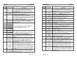
36

Software current 

limit exceeded

Please refer to the description of function code 
P8-36, P8-37.

37

Frequency lower 

limit reached 

(having output 

at stop)

38

Alarm output

When the inverter fails and the fault handling mode is 
continued, the ON signal is output.

39

Motor overheat

warning

When the motor temperature reaches P9-58, the 
output ON signal

40

Current running 

time reached

When the inverter runs for longer than P8-53, it 
outputs ON signal.

Setting 

value

Function

Instruction

When the running frequency reaches the lower limit 
frequency, the ON signal is output.
This signal is also ON during the stop state.

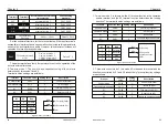
P5-06

Y2 pulse output function selection

Default: 0 running frequency

P5-07

AO output function selection

Default: 0 running frequency

P5-08

AO2 output function selection (extension)

Default: 1 set frequency


The  Y2  terminal  output  pulse  frequency  range  is  0.01  kHz  ~  P5-09 

(between 0.01 and 100.00 kHz).
 

The  analog  output AO1  and AO2  output  range  is  0V  ~  10V,  or  0mA  ~ 

20mA.  The  range  of  pulse  output  or  analog  output,  and  the  calibration 
relationship of the corresponding function are shown in the following table

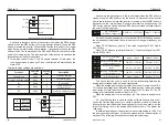
Set 

value

Function

Function corresponding to pulse or 

analog output 0.0%~100.0%

0

Running frequency

0 to the maximum output frequency

1

Set frequency

0 to the maximum output frequency

2

Output current

0 to 2 times the rated current of the motor

3

Output torque

0 to 2 times rated motor torque

4

Output Power

0 to 2 times rated power

5

Output voltage

0 to 1.2 times the rated voltage of the inverter

6

PULSE input

0.01kHz

100.00kHz

7

AI1

0V

10V

8

AI2

0V

10V

or 0

20mA

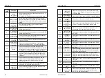
Set 

value

Function

Function corresponding to pulse or 

Analog output 0.0%~100.0%

9

AI3

0V

10V

10

Length

0 to the maximum set length

11

Count value

0 to the maximum count value

12

Communication 

setting

0.0% to 100.0%

13

Motor rotational 

speed

0 to the maximum output frequency corresponding 
to the speed

14

Output current

Output current 55KW and below 100% corresponds 
to 100.0A, 75KW and above 100% corresponds to
1000.0A

15

Output voltage 

(actual value)

(100% of the output voltage corresponds to 1000.0V) 
actually (1000.0V corresponds to 100% of the 
bus voltage)

P5-09

Y2 pulse output 

Maximum frequency

0.01kHz

100.00kHz

Default

50.00kHz


When the Y2 terminal is selected as the pulse output, the function code is 

used to select the Maximum frequency value of the output pulse.

AO zero offset coefficient

-100.0%

+100.0%

Default

0.0%

AO gain

-10.00

+10.00

Default

1.00

Extended AO2 zero 

offset coefficient

-100.0%

+100.0%

Default

0.0%

Extended AO2 gain

-10.00

+10.00

Default

1.00

P5-10

P5-11

P5-12

P5-13


The above function code is used to correct the zero drift of the analog 

output  and  the  deviation  of  the  output  amplitude.  It  can  also  be  used  to 
customize the required AO output curve. If the zero offset is represented by 
"b", the gain is represented by k, the actual output is represented by Y, and 
the standard output is represented by X, the actual output is: Y = kX + b. 
Among them, the zero offset coefficient of AO1 and AO2 corresponds to 10V 
(or  20mA),  and  the  standard  output  refers  to  the  output  of  0V~10V  (or 
0mA~20mA) corresponding to the analog output without zero offset and gain 
correction.

Chapter 6

Chapter 6

Содержание ATSEL FD300

Страница 1: ...ww selec europe com www selecaustralia com Selec USA Selec GmbH Selec Australia Selec Controls Pvt Ltd EL 27 1 Electronic Zone TTC Industrial Area MIDC Mahape Navi Mumbai 400710 INDIA Tel 91 22 4141 8...

Страница 2: ...t Please ensure to turn off the power when wiring The AC power cord must never be connected to the inverter output terminals U V W The inverter must be properly grounded There is a high voltage circui...

Страница 3: ...ection PA Process control PID function PB Swing frequency fixed length and counting PC Multi segment instruction and simple PLC function PP User password A0 Torque Control Function A5 Control optimiza...

Страница 4: ...braking DC braking frequency 0 00 Hz max frequency Braking time 0 0 100 0s Braking trigger current value 0 0 100 0 JOG control JOG frequency range 0 00Hz 50 00 Hz JOG acceleration deceleration time 0...

Страница 5: ...t terminal Standard 5 digital input DI terminals one of which supports up to 100 kHz high speed pulse input 2 analog input AI terminals support 0V 10 V voltage input or 0 mA 20 mA current input Expand...

Страница 6: ...m 100mm UP Right CONVERTER CONVERTER CONVERTER User Manual User Manual Chapter 2 Chapter 3 7 6 Installation size Power level 15kw 18 5 30kw 37kw 50mm 300mm 50mm 200mm 20mm 100mm A B WIRING In order to...

Страница 7: ...nnect a magnetic contactor MC in series to cut off the power supply when the inverter protection function is activated the R C surge absorber is required at both ends of the electromagnetic contactor...

Страница 8: ...B2 terminal is connected to the braking resistor there is B1 B2 terminal indicates that the inverter has built in braking unit 3 3 4 Inverter Grounding Terminal PE For safety and noise reduction the g...

Страница 9: ...ire 485 Positive signal 485 Communi cation 485 Negative signal KEYPAD OPERATION 4 1 Description of the keyboard panel Keyboard panel RUN When the light is off the inverter is in the stop state When th...

Страница 10: ...lect the function code Set the value of the function code Level I menu Level II menu Level III menu Example An example of changing the function code P3 02 from 10 00 Hz to 15 00 Hz black mark indicate...

Страница 11: ...Output current Bit7 Input status LED Running display parameters2 LED Stop display parameter P7 04 0000 FFFF Bit4 Remaining running time Bit6 AI2 Pre correction voltage V Bit0 PID Feedback Bit7 AI3 Pre...

Страница 12: ...d control mode selection Run command source selection Main frequency source X selection Preset frequency 0 00Hz Maximum frequency P0 10 50 00Hz Rotation direction 0 Maximum frequency 50 00Hz 500 00Hz...

Страница 13: ...eration time base frequency P0 26 0 running frequency 1 setting frequency 0 Fun ction Code Parameter Name Setting range Default Prope rty Modbus Address P0 27 Single digit Operation panel command bind...

Страница 14: ...c auto tuning 2 Complete auto tuning 3 Static full auto tuning 0 Fun ction Code Parameter Name Setting range Default Prope rty Modbus Address P2 Motor vector control parameter P2 00 Fun ction Code Par...

Страница 15: ...equency P1 04 0 00Hz 0 0 100 0 0 0 V F Slip compensation gain 0 0 200 0 0 0 0 200 64 V F oscillation suppression gain 0 100 Oscillation suppression mode selection 0 4 3 Voltage source for V F separati...

Страница 16: ...Setting range Default Prope rty Modbus Address P4 Multi functional inputs parameters P4 00 Fun ction Code Parameter Name Setting range Default Prope rty Modbus Address X1 Terminal function selection 1...

Страница 17: ...eration prohibition 22 PID pause 23 PLC reset 24 swing frequency pause 25 counter input 26 Counter reset 27 Length count input 28 Length reset 29 Torque control prohibited 30 Pulse frequency input 32...

Страница 18: ...election the same as above Hundreds AI3 is lower than the minimum input setting selection the same as above Fun ction Code Parameter Name Setting range Default Prope rty Modbus Address Unit s digit X1...

Страница 19: ...eady to RUN 16 AI1 AI2 17 Frequency upper limit reached 18 Frequency lower limit reached no output at stop 19 Under voltage status output 20 Communication setting 23 Zero speed running 2 having output...

Страница 20: ...imum frequency 0 00Hz P6 12 Waiting time of stop DC braking 0 0s 100 0s 0 0s P6 13 Stop DC braking current 0 100 0 P6 14 Stop DC braking time 0 0s 100 0s 0 0s P6 15 Brake use ratio 0 100 100 P6 18 Spe...

Страница 21: ...2 Hz Bit4 Remaining running time Bit5 AI1 pre correction voltage V Bit6 AI2 pre correction voltage V Bit7 AI3 pre correction voltage V Bit8 Linear speed Bit9 Current power on time Hour Fun ction Code...

Страница 22: ...ion 0 P8 19 Frequency detection value FDT1 0 00Hz Maximum frequency 50 00Hz P8 20 Frequency detection hysteresis value FDT1 0 0 100 0 FDT1 5 0 P8 21 Frequency arrival detection width 0 0 100 0 Maximum...

Страница 23: ...Wake up frequency P8 49 0 00Hz P8 52 Dormant delay time 0 0s 6500 0s 0 0s P8 53 Current running time reached 0 0Min 6500 0Min 0 0Min P8 54 Output power correction coefficient 0 00 200 0 100 0 Paramet...

Страница 24: ...t phase loss protection option Tens place Contactor suction protection option 0 Disabled 1 Enabled 0 no fault 1 Reserved 2 accelerated overcurrent 3 Deceleration over current 4 Constant speed over cur...

Страница 25: ...ace Input phase loss Err12 as above Hundreds place Output phase loss Err13 as above Thousands place External fault Err15 is the same as above Ten thousand communication abnormality Err16 is the same a...

Страница 26: ...s stop non stop integral coefficient Ki 0 100 30 P9 73 Instantaneous stop and stop motion deceleration time 0 300 0s 20 0s Parameter Name Setting Range Default Prope rty Modbus Address Fun ction Code...

Страница 27: ...aches the limit 0 Continue to integrate 1 Stop integral operation 0 0 PA 25 PID integral attribute 00 PA 26 PID feedback loss detection value 0 0 PID feedback loss detection time 0 0s 20 0s 0 0s PA 28...

Страница 28: ...0 0 PC 12 Multi segment instruction 12 0 0Hz P0 10 0 0 PC 13 Multi segment instruction 13 0 0Hz P0 10 0 0 PC 14 Multi segment instruction 14 0 0Hz P0 10 0 0 PC 15 Multi segment instruction 15 0 0Hz P0...

Страница 29: ...0s h 6553 5s h 0 0s h 6553 5s h 0 0s h 0 0s h 0 0s h PC 37 PC 39 PC 41 0 3 0 3 0 3 0 0 0 Section 9 acc and dec time selection Section 10 acc and dec time selection Section 11 acc and dec time selectio...

Страница 30: ...Prope rty Modbus Address Fun ction Code PE 00 User function code 0 U3 17 PE 01 User function code 1 U3 16 PE 02 User function code 2 P0 00 Res erved Reserved Reserved PE 28 User function code 28 P0 0...

Страница 31: ...depth 0 Invalid 1 10 Random PWM depth 0 A5 04 Rapid current limit 0 Invalid 1 Valid 1 A5 05 Current detection compensation 0 100 0 A5 06 Under voltage threshold 60 0 140 0 100 0 A5 07 SVC optimization...

Страница 32: ...ction Code Fun ction Code Parameter Name Setting range Default Prope rty Modbus Address AC AIAO checking Fun ction Code Parameter Name Setting range Default Prope rty Modbus Address AC 00 AI1 measured...

Страница 33: ...ut power kW U0 06 Output torque 200 0 200 0 Display inverter output torque during operation U0 07 Input terminal status 0 32767 Input status X1 X9 corresponds to Bit0 Bit8 U0 08 Output terminal status...

Страница 34: ...us machine rotor position U0 34 Motor tem perature value 1 Display motor temperature value U0 35 Target torque 0 1 Display target torque U0 36 Rotational position 1 Display the position of the rotatio...

Страница 35: ...command channel LED off 1 terminal command channel LED is lit 2 Communication command channel LED flashing Default 0 1 Terminal command channel L R is on which is controlled by the multi function inpu...

Страница 36: ...When the auxiliary frequency source Y is used as an independent frequency reference channel X to Y switching its usage is the same as that of the main frequency source X P0 03 Note when the auxiliary...

Страница 37: ...requency source Y is used as the target frequency 2 Take the maximum of the absolute value of the main frequency X and the auxiliary frequencyYas the target frequency the offset frequency is set by P0...

Страница 38: ...temperature 0 no 1 yes Default 1 When the inverter detects that its own temperature is high it automatically reduces the carrier frequency to reduce the temperature rise of the inverter When the tempe...

Страница 39: ...rminal selection is subject to P0 25 Acceleration Deceleration time base frequency 0 Maximum frequency P0 10 1 Set frequency 2 100Hz Default 0 Acceleration deceleration time refers to the acceleration...

Страница 40: ...l automatically modify the P1 06 P1 10 parameter values and restore these five parameters to the common standard Y series motor parameters If the asynchronous motor cannot be tuned at the site you can...

Страница 41: ...loop integration time 2 0 01s 10 00s Default 1 00s Switchover frequency 2 P2 02 Maximum frequency Default 10 00Hz P2 Vector control parameter P2 function code is valid only for vector control and inv...

Страница 42: ...Pulse setting 5 Communication setting 6 MIN AI1 AI2 7 MAX AI1 AI2 The full scale of the 1 7 option corresponds to P2 10 Default 0 Digital setting of torque upper limit in speed control mode 0 0 200 0...

Страница 43: ...centrifugal loads such as fans and pumps 10 V F complete separation mode At this time the output frequency of the inverter is independent of the output voltage the output frequency is determined by t...

Страница 44: ...ferent from the target value the gain needs to be fine tuned appropriately V F Over excitation gain 0 200 Default 120 P3 10 During the deceleration the over excitation control can suppress the rise of...

Страница 45: ...ils see the introduction of the PAgroup PID 4 Pulse setting the voltage reference is given by the terminal pulse 5 ulti segment command when the voltage source is a multi segment command set the P4 gr...

Страница 46: ...stall current exceeding the rated frequency fs fn k Limit Cur If the bus voltage exceeds the overvoltage stall point of 760V indicating that the electromechanical system is already in the power genera...

Страница 47: ...frequency is incremented or decremented when the frequency is given by the external terminal When the frequency source is set to digital setting the set frequency can be adjusted up and down 7 Termin...

Страница 48: ...utton function on the keyboard 37 Command source switchover terminal 2 Used for switching between terminal control and communication control If the command source is selected as the terminal control t...

Страница 49: ...Multi segment instruction 15 PC 15 ON ON ON ON Schedule 2 Acceleration deceleration time selection terminal function description When the frequency source is selected as multi speed 100 0 of function...

Страница 50: ...If the input terminal is susceptible to interference and cause malfunction increase this parameter to enhance the anti interference ability However this parameter increase will cause the X terminal to...

Страница 51: ...se refer to the description of each part The following illustrations are for two typical settings When the analog input is a current input the 1mA current is equivalent to 0 5V The above function code...

Страница 52: ...nding value 100 0 100 0 Default 100 0 Pulse input filtering time 0 00s 10 00s Default 0 10s This group of function codes is used to set the relationship between the multi function terminal X6 pulse in...

Страница 53: ...mode of the digital input terminal 0 Positive logic the corresponding terminal is valid when connected to COM and the disconnection is invalid P5 Output terminal The inverter comes standard with one...

Страница 54: ...ruction When the inverter runs and the output frequency is 0 the ON signal is output This signal is OFF when the drive is in the stop state 18 Frequency lower limit reached no output at stop When the...

Страница 55: ...1 2 times the rated voltage of the inverter 6 PULSE input 0 01kHz 100 00kHz 7 AI1 0V 10V 8 AI2 0V 10V or 0 20mA Set value Function Function corresponding to pulse or Analog output 0 0 100 0 9 AI3 0V 1...

Страница 56: ...the pre excitation time is not 0 the pre excitation is restarted first which can improve the dynamic response performance of the motor 0 Direct start if the DC braking time is 0 the inverter will star...

Страница 57: ...er Acceleration Deceleration mode Default 0 P6 07 0 Linear acceleration and deceleration 1 S curve acceleration and deceleration A 2 S curve acceleration and deceleration B The output frequency is inc...

Страница 58: ...op DC braking time 0 0s 100 0s Default 0 0s P6 11 P6 12 P6 13 P6 14 DC braking start frequency at stop When the inverter stops when the running frequency decreases to this frequency DC braking starts...

Страница 59: ...y can be set by this function code This key can be used to switch between stop and run 3 Forward jog through the keyboard JOG REV Key to achieve forward jog 4 Reverse jog through the keyboard JOG REV...

Страница 60: ...Frequency setting Bus voltage X input statue Output statue AI 1 voltage AI 2 voltage AI 3 voltage Count value 15 14 13 12 11 10 9 8 Length value PLC stage Overload speed PID setting Pulse input Reser...

Страница 61: ...d to the direct start mode P 6 0 0 0 and the stop mode is fixed to the deceleration stop P6 10 0 Acceleration time 1 0 0s 6500 0s depend Deceleration time 1 0 0s 6500 0s depend Acceleration time 2 0 0...

Страница 62: ...ng the same load The droop control means that as the load increases the output frequency of the inverter decreases so that when multiple motors are dragged by the same load the output frequency of the...

Страница 63: ...requency relative to the frequency detection value P8 19 Figure 6 18 shows the function of the FDTfunction Figure 6 18 FDT level diagram Output frequency Hz FDT level Frequency arrival detection signa...

Страница 64: ...2 is selected if the running frequency is greater than P8 25 the acceleration time 1 is selected During deceleration if the running frequency is greater than P8 26 the deceleration time 1 is selected...

Страница 65: ...cted 0 1 300 0 motor rated current Default 200 0 P8 37 Output overcurrent detection delay time 0 00s 600 00s Default 0 00 When the output current of the inverter is greater than or exceeds the detecti...

Страница 66: ...0 0 The fan is running during operation 1 The fan is always running Used to select the action mode of the cooling fan 0 The fan runs in the running state If the radiator temperature is higher than 40...

Страница 67: ...fault 30 P9 04 Overvoltage stall protective voltage 120 150 Default 760V When the DC bus voltage exceeds the value of P9 04 Overvoltage stall protective voltage during deceleration of the inverter the...

Страница 68: ...ic fault reset P9 12 Input phase loss protection option 0 Prohibited 1 Allowed Default 1 The inverter has the input phase loss protection function from the 18 5kW G type machine and above The power of...

Страница 69: ...at the first failure Fault protection action selection 1 Default 00000 Fault protection action selection 3 BIT4 BIT3 BIT2 BIT1 BIT0 P9 28 P9 29 P9 30 P9 31 P9 32 P9 33 P9 34 P9 37 P9 38 P9 39 P9 40 P9...

Страница 70: ...ailure voltage rise judgment time 000 0s 100 0s Default 0 5s Instantaneous power failure action judgment voltage 60 0 100 0 standard bus voltage Default 80 0 P9 60 P9 61 P9 62 This function means that...

Страница 71: ...erter will continue to decelerate to 0Hz and stop until the inverter issues the start command again 2 The purpose of instantaneous stop is to ensure that when the power supply of the power grid is abn...

Страница 72: ...nt The shorter the integration time the greater the adjustment intensity The integration time means that when the deviation between the PID feedback amount and the given amount is 100 0 the integral r...

Страница 73: ...multi function terminal function selection should be set to 43 PID parameter switching terminal When the terminal is invalid select parameter group 1 PA 05 PA 07 When the terminal is valid select the...

Страница 74: ...center and the running frequency is in the time axis As shown in Figure 6 31 the swing amplitude is set by PB 00 and PB 01 When PB 01 is set to 0 the swing is 0 At this time the swing frequency does...

Страница 75: ...th PB 05 the output length reaches the ON signal During the fixed length control the length reset operation can be performed through the input terminal 28 In the application the corresponding input te...

Страница 76: ...source the positive and negative of PC 00 PC 15 determine the running direction If it is negative it means the inverter runs in the opposite direction Figure 6 33 Simple PLC schematic 2 Always cycle...

Страница 77: ...0 Section 7 Acc and dec time selection Section 8 Acc and dec time selection The 9th paragraph Acc and dec time selection Section 10 Acc and dec time selection Section 5 Acc and dec time selection PC 4...

Страница 78: ...roup display selection Function parameter group display selection Function code modification attribute 0 Can be modified 1 not modifiable Default 0 Default 11 PP 04 Whether the user can set the functi...

Страница 79: ...not need to be modified Only when there is a special requirement for the quality of the output voltage waveform or when the motor has an abnormality such as oscillation it is necessary to try to switc...

Страница 80: ...ection point 1 input corresponding setting 100 0 100 0 Default 30 AI curve 4 inflection point 2 input A6 02 A6 06 Default 6 00V AI curve 4 inflection point 2 input corresponding setting 100 0 100 0 De...

Страница 81: ...reset factory reset factory reset factory reset factory reset AC 01 AC 02 AC 03 AC 04 AC 05 AC 06 AC 07 AC 08 AC 09 AC 10 AC 11 factory reset factory reset factory reset factory reset This set of func...

Страница 82: ...tips in this section to analyze the cause of the fault If the fault cannot be solved please seek technical support from our company or product agent Fault name Display Troubleshoot the cause Solution...

Страница 83: ...stall the braking resistor 1 Instantaneous power failure occurs on the input power supply 2 The AC drive s input voltage is not within the allowable range 3 The bus voltage is abnormal 4 The rectifier...

Страница 84: ...supply are faulty 2 The contactor is faulty 3 Three phase input power shortage 1 Replace the faulty driver board or power supply board 2 Replace the faulty contactor 3 check the three phase input powe...

Страница 85: ...e control board or the operating panel is faulty 5 The cable connecting the control board and the driver board and the operating panel breaks 1 Check the power supply 2 Check the bus voltage 3 Re conn...

Страница 86: ...E Inspection and maintenance of the inverter requires professional and qualified personnel and pay attention to the following matters Maintenance personnel must follow the specified methods of mainten...

Страница 87: ...void storage in environments containing corrosive gases and liquids Long term storage will lead to deterioration of electrolytic capacitors It is best to ensure that the power is turned on within 2 ye...

Страница 88: ...nication protocol defines the transmission information and use format in the series communication and it includes master polling or broadcasting format master coding method and the content includes fu...

Страница 89: ...function code n CRC correction and H L Free Calculate CRC correction 1byte 2nbyte 2byte Master writes command frame 3 5byte 1byte 2byte Free Start frame Target station address Read the command 0x06 Fu...

Страница 90: ...s extracted and examined If the LSB was a 1 the register is then exclusive Oared with a preset fixed value If the LSB was a 0 no exclusive OR takes place This process is repeated until eight shifts ha...

Страница 91: ...l 4123 Present power on time 4107 AI1 voltage 4124 Present running time 4108 AI2 voltage 4125 Pulse input frequency unit 1Hz 4109 AI3 voltage 4126 Communication setting value 4110 Counting value input...

Страница 92: ...fault during running 002A Too large speed deviation 002B Motor over speed 002D Motor overheat 005A Encode lines setting fault 005B Not connect to the encoder 005C Initial location fault 005E Speed fe...

Страница 93: ...r power and resistance values for this drive According to the load the user can change the value appropriately but it cannot be less than the minimum required by the inverter During the running proces...

Страница 94: ...00 598 620 390 300 11 350 745 780 480 360 12 Overall dimensions and mounting whole dimensions of the Keypad base and the Operating keyboard Chapter 9 FD300 3 050 C CE FD300 3 075 C CE FD300 3 100 C CE...

Отзывы: