User Manual
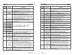
10.2.2 For VFD200 Series
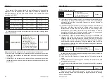
Digital setting, Analog Voltage setting,
Analog Current setting
Forward/Reverse, Jogging selection, Multi
Speed Control, Regular Stopping
Fault Alarm Output (250V/2A Contact),
Open Collector Output
Over Current, Over Voltage, Under Voltage,
Over heat, Overload, Phase loss
Parameters setting, Running status and
Fault display
Temperature: -10 ~ +50 Degree C, Humidity:
< 90%, No condensation, IP20
Indoor, <1000m altitude above sea level
-20 ~ +60 Degree C
2
<5.9 m/s (0.6g)
Operation
Commands
Input Signal
Output signal
Operating
conditions
Operating
environment
Operations Area
Storage
Temperature
Vibration
Operation
Function
Display
Frequency
Setting
Keypad and External terminals
Protection Functions
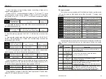
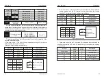
Rated
Power kW
Output
current A
0.7 1.5 2.2 0.7 1.5 2.2
4
5.5 7.5 11
15 18.5 22
30
7
11 2.5 3.7 5.5
9
13
17
25
32
38
45
60
Rated
Power kW
Output
current A
37
45
55
75
90
110 132 160 185 200 220 250 280 315
75
90 110 150 176 210 250 300 340 380 420 470 520 585
Rated
voltage V
Single-phase
220V
Three-phase 415V
Rated
voltage V
Three-phase 415V
5
Specifications
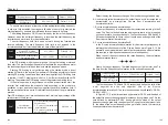
3 phase 415V 50Hz/60 Hz.
320 to 460V for 3 Phase
±5%
Space Vector SVPWM and Flux Vector Control
0.1 ~ 400 Hz.
Digital setting 0.01%, Analog instruction 0.1%
(Max frequency)
Digital instruction 0.1Hz, Analog instruction
0.1Hz.
0.0 ~3600s,four accelerate/decelerated time
settings available
Build-in program
Easy to consist a simple automatic control system
Power
supply
Rated input
voltage/ frequeny
Permissible frequency
fluctuation
Control mode
Frequency accuracy
Frequency
resolution
Accelerated\
decelerated time
Multi Speed
running
Build-in PI
Permissible voltage
fluctuation
Control
charact-
eristic
Digital setting, Analog Voltage setting,
Analog Current setting
Forward/Reverse, Jogging selection, Multi
Speed Control, Regular Stopping
Fault Alarm Output (250V/2A Contact), Open
Collector Output
Operation
function
Keypad and External terminals
Frequency Control
range
Build-in counter
Overload capacity
Braking torque
V/F mode
Automatic Energy
saving operation
Automatic Voltage
Regulation
Automatically controlled Production line can
be achieved
G Type - 150% rated current for 1 min. P type -
120% rated current for 1 min
About 20% (with brake resistor is about 150%)
3 preset V/F mode and V/F program
Changes the V/F curve according to the load
to save energy
Regulates the voltage automatically when there
is change in grid voltage
Operation Commands
Input signal
Output signal
Frequency Setting
User Manual
85
84
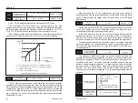
V/F separation is generally used in induction heating, inverter power
supply and torque motor control.
When V/F separation control is selected, the output voltage can be set by
function code P3-14, or it can be from analog quantity, multi-segment
instruction, PLC, PID or communication reference. When using non-digital
setting, 100% of each setting corresponds to the rated voltage of the motor.
When the percentage of the output setting such as analog quantity is
negative, the set absolute value is used as the effective setting value.
0 : Digital setting (P3-14) the voltage is set directly by P3-14.
1 : AI1 2: AI2
3 : The AI3 voltage is determined by the analog input terminal.
6 : When the simple PLC voltage source is a simple PLC, you need to set the
PC group parameters to determine the given output voltage.
8 : Communication reference the voltage is given by the host computer
through communication.
When the above voltage source is selected from 1 to 8, 0 to 100%
corresponds to the output voltage 0V to the motor rated voltage.
7 : PID: The output voltage is generated according to the PID closed loop. For
details, see the introduction of the PA group PID.
4 : Pulse setting the voltage reference is given by the terminal pulse.
5 : ulti-segment command when the voltage source is a multi-segment
command, set the P4 group and PC group parameters to determine the
output voltage.
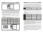
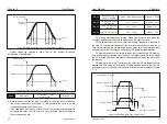
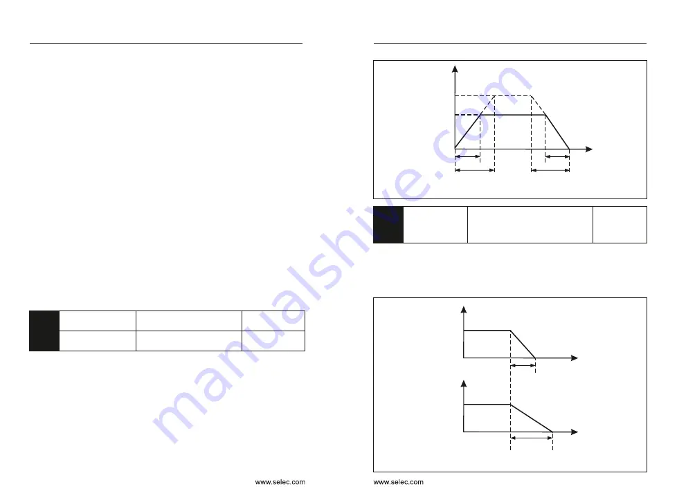
Actual acceleration time
Actual
deceleration time
Set deceleration time
Set acceleration time
Target voltage
Motor rated voltage
Output voltage
Figure 6-5 V/F Separation diagram
t1
t2
Voltage rise time
of V/F separation
0.0s
〜
1000.0s
Default
:
0.0s
Voltage decline time
of V/F separation
0.0s
〜
1000.0s
Default
:
0.0s
P3-15
P3-16
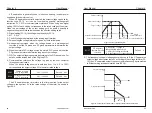
The V/F separation rise time refers to the time required for the output
voltage to change from 0V to the rated voltage of the motor. As shown in
Figure 6-5.
V/F Separate
shutdown mode
selection
0: frequency / voltage is
independently reduced to 0
1: After the voltage is reduced
to 0, the frequency is reduced again.
Default
:
0
P3-17
0
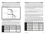
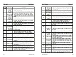
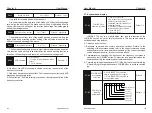
: The frequency/voltage is independently reduced to 0; the V/F separated
output voltage is decremented to 0V according to the voltage fall time (P3-
15); the V/F separated output frequency is simultaneously decremented
to 0Hz according to the deceleration time (P0-18).
Output voltage
Figure 6-6 V/F Separate output voltage / frequency independently reduced to 0
Output frequency
t1
P3-15
t2
P0-18
Chapter 6
Chapter 6


