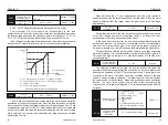
These parameters above are mainly applied to the setting of seven
different phase speeds; principal frequency is still controlled by parameter
P0-03.
First phase speed
Default:
11.0Hz
P8-01
Lower limiting frequency
~
Upper limiting frequency
Second phase
speed
P8-02
Lower limiting frequency
~
Upper limiting frequency
Third phase speed
P8-03
Lower limiting frequency
~
Upper limiting frequency
Forth phase speed
P8-04
Lower limiting frequency
~
Upper limiting frequency
Fifth phase speed
P8-05
Lower limiting frequency
~
Upper limiting frequency
Sixth phase speed
P8-06
Lower limiting frequency
~
Upper limiting frequency
Seventh phase
speed
P8-07
Lower limiting frequency
~
Upper limiting frequency
Default:
12.0Hz
Default:
13.0Hz
Default:
14.0Hz
Default:
15.0Hz
Default:
16.0Hz
Default:
17.0Hz
Runtime of
principal frequency
P8-08
Default:
0.0
First phase time
Default:
0.0
P8-09
Second phase
time
P8-10
Third phase time
P8-11
Forth phase time
P8-12
Fifth phase time
P8-13
Sixth phase time
P8-14
Seventh phase
time
P8-15
Default:
0.0
Default:
0.0
Default:
0.0
Default:
0.0
Default:
0.0
Default:
0.0
0
~
6400.0
0
~
6400.0
0
~
6400.0
0
~
6400.0
0
~
6400.0
0
~
6400.0
0
~
6400.0
0
~
6400.0
Time unit of
multi-velocity
P8-16
Default: 0
0 : second
1 : minute
2 : hour
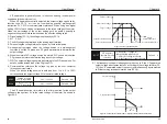
These parameters from P8-08 to P8-15 are mainly applied to the
setting of run time for the velocity of each phase. Time unit can be preset by
parameter P8-16.
It’s mainly applied to the setting of running directions for each program, which
is preset by binary mode (8 bit). Parameter can be entered only after the
binary value is converted into decimal value. Take the following settings for
example:
Running directions
of programs
Default: 0
P8-17
0~255
BIT 0~7 indicates 0~7 directions
(0: Forward 1: Reverse)
P8-07
P8-04
P8-06
P8-05
P8-01
P8-02
P8-03
P8-03
P8-08
P8-09
P8-10
P8-11
P8-13
P8-14
P8-15
P8-12
Frequency (Hz)
FWD
Time (t)
REV
Weighted value
BIT
Binary set value
0 : Forward
1 : Reverse
Running directions of Principle frequency: FWD
Running directions of first phase: REV
Running directions of second phase: FWD
Running directions of third phase: REV
Running directions of forth phase: FWD Running
directions of fifth phase: FWD
Running directions of sixth phase: REV
Running directions of seventh phase: FWD
0
7
2
0
0
0
0
6
2
5
2
4
2
3
2
2
2
1
2
0
2
1
1
1
7
5
4
2
0
6
1
3
59
58
A6-06
AI curve 4
maximum
input
A6-06
〜
+10.00V
10.00V
A6-07
AI curve 4
maximum input
correspon-
ding setting
-100.0%
〜
+100.0%
100.0%
A6-08
AI curve 5
minimum input
-10.00V
〜
A6-10
-10.00V
A6-09
AI curve 5
minimum input
correspon-
ding setting
-100.0%
〜
+100.0%
-100.0%
A6-10
AI curve 5
inflection point
1 input
A6-08
〜
A6-12
-3.00V
A6-11
AI curve 5
inflection point
1 input
correspon-
ding setting
-100.0%
〜
+100.0%
-30.0%
A6-12
AI curve 5
inflection point
2 input
A6-10
〜
A6-14
3.00V
A6-13
AI curve 5
inflection point
2 input
correspon-
ding setting
-100.0%
〜
+100.0%
30.0%
A6-14
AI curve 5
maximum
input
A6-12
〜
+10.00V
10.00V
A6-15
AI curve 5
maximum input
correspon-
ding setting
-100.0%
〜
+100.0%
100.0%
A6-24
AI1 sets the
jump point
-100.0%
〜
100.0%
0.0%
A6-25
AI1 sets the
jump range
0.0%
〜
100.0%
0.5%
A6-26
AI2 sets the
jump point
-100.0%
〜
100.0%
0.0%
A6-27
AI2 sets the
jump range
0.0%
〜
100.0%
0.5%
A6-28
AI3 sets the
jump point
-100.0%
〜
100.0%
0.0%
A6-29
AI3 sets the
jump range
0.0%
〜
100.0%
0.5%
Parameter
Name
Setting Range
Default
Prope-
rty
Modbus
Address
Fun-
ction
Code
Fun-
ction
Code
Parameter
Name
Setting range
Default
Prope-
rty
Modbus
Address
AC: AIAO checking
Fun-
ction
Code
Parameter
Name
Setting range
Default
Prope-
rty
Modbus
Address
AC-00
AI1 measured
voltage 1
-10.00V
〜
+10.00V
factory
reset
AC-01
AI1 display
voltage 1
-10.00V
〜
+10.00V
AC-02
AI1 measured
voltage 2
6.000V
〜
9.999V
AC-03
AI1 display
voltage 2
6.000V
〜
9.999V
AC-04
AI2 measured
voltage 1
0.500V
〜
4.000V
AC-05
AI2 display
voltage 1
0.500V
〜
4.000V
AC-06
AI2 measured
voltage 2
6.000V
〜
9.999V
AC-07
AI2 display
voltage 2
6.000V
〜
9.999V
AC-08
AI3 measured
voltage 1
-9.999V
〜
10.000V
AC-09
AI3 display
voltage 1
-9.999V
〜
10.000V
AC-10
AI3 measured
voltage 2
-9.999V
〜
10.000V
AC-11
AI3 display
voltage 2
-9.999V
〜
10.000V
AC-12
AO1 target
voltage 1
0.500V
〜
4.000V
AC-13
AO1 measured
voltage 1
0.500V
〜
4.000V
factory
reset
factory
reset
factory
reset
factory
reset
factory
reset
factory
reset
factory
reset
factory
reset
factory
reset
factory
reset
factory
reset
factory
reset
factory
reset
User Manual
Chapter 5
User Manual
Chapter 5
○
○
○
○
○
○
○
○
○
○
○
○
○
○
○
○
○
○
○
○
○
○
○
○
○
○
○
○
○
○
42503
42504
42505
42506
42507
42508
42509
42510
42511
42512
42521
42522
42523
42524
42525
42526
44033
44034
44035
44036
44037
44038
44039
44040
44041
44042
44043
44044
44045
44046
-10.00V
〜
+10.00V
-10.00V
〜
+10.00V
-10.00V
〜
+10.00V
-10.00V
〜
+10.00V
-10.00V
〜
+10.00V
-10.00V
〜
+10.00V
-10.00V
〜
+10.00V
-10.00V
〜
+10.00V
-10.00V
〜
+10.00V
-10.00V
〜
+10.00V
-10.00V
〜
+10.00V
-10.00V
〜
+10.00V


