User Manual
APPENDIX
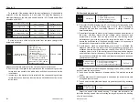
10-1 List of braking resistor
If controlled motor decelerates too fast, or load jittering of motor is too fast
while converter is running, its electromotive force will charge the internal
capacitors of converter through converter's reverse function, which will rise
the voltage of power module and damage converter. However, this will be
restrained by converter's internal control according to the condition of
loading; additional braking resistor needs to be installed externally to release
the power in time when braking performance doesn't meet customers'
requirements. External braking resistor works by consuming energy which
will be consumed completely by power braking resistor; therefore, power and
resistance of braking resistor must be applicable and effective. Braking
resistors whose power and resistance value are as followed are
recommended to be applied to this converter. According to the condition of
loading, value can be changed properly; but it must be no less than the
minimum of this converter
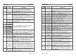
FD300-3-075-C-CE
500W 90Ω
60Ω
FD300-3-100-C-CE
800W 60Ω
47Ω
FD300-3-150-C-CE
1000W 47Ω
36Ω
FD300-3-200-C-CE
1500W 36Ω
27Ω
FD300-3-250-C-CE
~
FD300-3-1000-C-CE
According to the require-
ments of brake units and
recommended to choose
For FD100
Due to the energy consumption of braking resistor, a mass of heat may be
generated if it keeps braking frequently; therefore, safety and Inflammability
of the surrounding must be taken into consideration
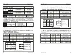
Converter Power
Recommended
resistance
Minimum resistance
FD100-1-0-10-C-CE
150W 400Ω
260Ω
FD100-1-0-20-C-CE
FD100-1-0-30-C-CE
200Ω
150Ω
200W 300Ω
250W 200Ω
For FD300
Converter Power
Recommended
resistance
Minimum resistance
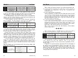
10.2.1 For VFD100
Three-Phase 415V
Single Phase 220V 50Hz/60Hz,
3 Phase 415V 50Hz/60Hz.
187V to 253V for 1 phase & 320 to 460V
for 3 Phase
Space Vector SVPWM and Flux Vector Control
0.1 ~ 400 Hz.
Digital setting 0.01%, Analog instruction
0.1% (Max frequency)
Digital instruction 0.1Hz, Analog instruction
0.1 Hz.
0.0 ~ 3600 Sec. Four accelerate/decelerate
time settings available
Built-in program
Easy to set up a simple Automatic control
system
Automatically Controlled Production line can
be achieved
G Type - 150% rated current for 1 min.
P type - 120% rated current for 1 min
About 20% (with brake resistor is about 150%)
3 preset V/F mode and V/F program
Changes the V/F curve according to the
load to save energy
Regulates the voltage automatically when-
ever there is a change in grid voltage
Power
supply
Rated input voltage/
frequeny
Permissible frequency
fluctuation
Control mode
Frequency Control
range
Frequency Accuracy
Frequency resolution
Accelerated/decele-
ratedtime
Multi Speed running
Built-in PI
Built-in Counter
Overload Capacity
Braking torque
V/F mode
Automatic Energy
Saving Operation
Automatic Voltage
Regulation
Permissible voltage
fluctuation
Control
Charact-
eristic
±5%
Specifications
Rated Power kW
Output current A
Rated voltage V
Single-phase
220V
0.7
1.5
2.2
0.7
1.5
2.2
5
7
11
2.5
3.7
5.1
User Manual
83
82
Multi-point V/F
frequency point 3
P3-05
~
motor rated frequency
(
P1-04
)
Default
:
0.00Hz
Multi-point V/F
voltage point 3
0.0%
〜
100.0%
Default
:
0.0%
P3-07
P3-08
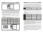
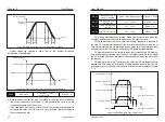
The multi-point V/F curve should be set according to the load
characteristics of the motor. It should be noted that the relationship between
the three voltage points and the frequency point must satisfy: V1 < V2 < V3,
F1 < F2 < F3. Figure 6-4 shows the setting of the multi-point V/F curve.
P3-03
〜
P3-08 Six parameters define multi-segment V/F curves
。
If the voltage is set too high at low frequencies, the motor may overheat or
even burn out. The inverter may over-current or over-current protection.
F3
Fb
F2
F1
V1
V2
V3
Vb
voltage%
Frequency%
V1-V3: Multi-speed V/F section 1-3 voltage percentage
F1-F3: Multi-speed V/F section 1-3 frequency percentage
Vb : Motor rated voltage
Fb : Motor rated running frequency
Output frequency
Figure 6-4 Multi-point V/F curve setting diagram
V/F Slip
compensation gain
0.0%
〜
200.0%
Default
:
0.0%
P3-09
The V/F slip compensation can compensate the motor speed deviation
generated by the asynchronous motor when the load increases, so that the
motor speed can be basically stabilized when the load changes. The VF slip
compensation gain is set to 100.0%, which means that the motor's rated slip
is the motor's rated slip when the rated load is applied, and the motor's rated
slip is obtained. The inverter is calculated by the rated frequency and rated
speed of the P1 motor.
When adjusting the V/F slip compensation gain, the motor speed is
basically the same as the target speed under the rated load. When the motor
speed is different from the target value, the gain needs to be fine-tuned
appropriately.
V/F Over-
excitation gain
0
〜
200
Default
:
120
P3-10
During the deceleration, the over-excitation control can suppress the rise
of the bus voltage and avoid overvoltage faults. The larger the over-
excitation gain, the stronger the suppression effect.
In the case where the inverter is easy to overvoltage alarm during the
deceleration process, it is necessary to increase the over-excitation gain.
However, the over-excitation gain is too large, which tends to cause an
increase in the output current, which needs to be weighed in the application.
For applications where the inertia is small, there is no voltage rise during
motor deceleration. It is recommended to set the over-excitation gain to 0.
For those with braking resistors, it is also recommended to set the over-
excitation gain to 0.
V/F oscillation
suppression gain
0
〜
100
depend
P3-11
The selection method of the gain is as small as possible under the
premise of effectively suppressing the oscillation, so as to avoid adversely
affecting the operation of the V/F. Select this gain to be 0 when there is no
oscillation in the motor. Only when the motor oscillates obviously, the gain
needs to be appropriately increased. The larger the gain, the more obvious
the suppression of the oscillation. When using the suppression oscillation
function, the motor rated current and no-load current parameters are
required to be accurate, otherwise the V/F oscillation suppression effect is
not good.
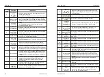
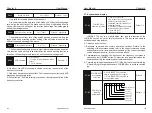
Voltage source for
V/F separation
0: Digital setting (P3-14)
1: AI1 2: AI2 3: AI3
4: Pulse setting (X6)
5: Multi-speed
6: Simple PLC
7: PID
8: Communication reference
(100.0% corresponds to rated
voltage)
Default
:
0
Voltage digital
setting for V/F
separation
0V ~ motor rated voltage
Default
:
0V
P3-13
P3-14
Chapter 6
Chapter 6


