User Manual
User Manual
69
68
1. R/W errors of
parameter
2. Damage of
EEPROM
EEP
1
EEPROM
fault
1. Factory reset
2. Seek technical
support for damages
1. please refer to
fault cause of over
current (OC)
2. short circuit of
output terminal
(U,V,W) or earth
terminal
3. loose plug-in units
or wiring of control
panel
4. damages of power
module or other
parts
Output
failure
Fault
indication
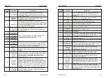
Code Fault type
Fault cause
Solutions
SC
9
Short-
circuit
output
1. Please refer to
solutions for over
current(OC)
2. Check the state of
insulation (motor &
cable)
3. Check the connection
of plug-in units
4. Seek technical
support for damages
SPI
7
Input
Failure
default phase of
power source R,S,T
1. Check power source
and its voltage
2. Check the connection
of power line
SPO
8
1. Default phase of
output terminals
U
,
V
,
W
2. Unsymmetrical
three-phase load
1. Check the output line
connection
2. Check motor and
its cables
Overheat
OH
13
1. High ambient
temperature
2. Obstruction of
ventilation duct or
damage of cooling
fan
3. Excessive motor
load
1. Lower the ambient
temperature
2. Clear the ventilation
duct and replace the
cooling fan
3. Reduce motor load
or carrier frequency
PIE
12
PI Fault
No detection of PI
feedback signal
for a certain time
Check on PI feedback
signal and connection
EF
11
External
fault
Input terminal for
external fault signal
is enabled
Check the input of
external devices
OPSE
10
System
failure
Severe interface
external factors,
e.g. noise
install additional
filter or seek
technical support
for damages
CF
20
The current
detecting
signal
failure
1. The current
sensor is damaged
2. Signal lines,
poor contact
3. Other line fault
7-2 Common Faults and Processing Schemes
If the following situations are met during the application of converter;
please refer to the instructions below:
•
No information display after power on
Please check if power indicator is on or not; if it's off, malfunction is mainly
caused by abnormal rectifier and buffer resistance; if it's on, malfunction is
mainly caused by switching power supply. Meanwhile, please seek for
technical support.
Please confirm whether the voltage of power source is compatible with
the rated voltage of converter.
Please check whether three-phase rectifier bridge is in good condition; if
it's damaged, please seek for technical support.
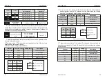
Fault
indication
Code
Fault type
Fault cause
Solutions
1. low voltage of grid
2. damage of
contactor
3. the other damaged
circuit
NCE
16
Contactor
fault
1. Check the voltage of
grid
2. Replace the contactor
of major loop
3. Seek technical support
for damages
1. Change the current
sensor
2. Check the Signal line
3. Seeking services
CE
21
communi-
cation
failure
Poor communication
or broken
communication line
Check if the communi-
cation settings are
correct or communi-
cation.
Whether the wire is
disconnected or has
poor contact
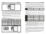
The frequency reference channel is selected by this parameter.
Frequency reference is realized by the combination of the main frequency
source X and the auxiliary frequency source Y.
Ones place :
Frequency source selection:
0 : The main frequency source X frequency X is the target frequency.
1 : Main and auxiliary operation results the main and auxiliary operation
results are used as the target frequency, and the main and auxiliary
operation relationships are described in the "ten place".
2 : Main frequency source X and auxiliary frequency source Y are switched.
When input terminal function P4-00~09 is set to 18.Input terminal
(frequency source switching) is invalid: main frequency X is the target
frequency; the input terminal (frequency source switching) is valid: the
auxiliary frequency Y is the target frequency.
3 : Main frequency source X and main and auxiliary operation result switching
When input terminal function P4-00~09 is set to 18.Input terminal
(frequency source switching) is invalid: main frequency source X is the
target frequency; The input terminal (frequency source switching) is valid:
the result of the main and auxiliary operations is used as the target
frequency.
4 : Auxiliary frequency source Y and main and auxiliary operation result
switching When input terminal function P4-00~09 is set to 18.Invalid input
terminal: auxiliary frequency Y as the target frequency; The input terminal
is valid: the result of the main and auxiliary operations is used as the target
frequency.
Tens place: frequency source primary and secondary operation
relationship:
0 : Main frequency source X + auxiliary frequency source Y is used as the
target frequency. Achieve frequency superposition given function.
3 : Taking the absolute value of the main frequency X and the auxiliary
frequency Y as the minimum target frequency.
When the frequency source is selected as the main and auxiliary operation,
1 : Main frequency source X-auxiliary frequency source Y is used as the
target frequency.
2 : Take the maximum of the absolute value of the main frequency X and the
auxiliary frequency Y as the target frequency.
the offset frequency is set by P0-21, and the offset frequency is
superimposed on the result of the main and auxiliary operations.
Default
:
50.00Hz
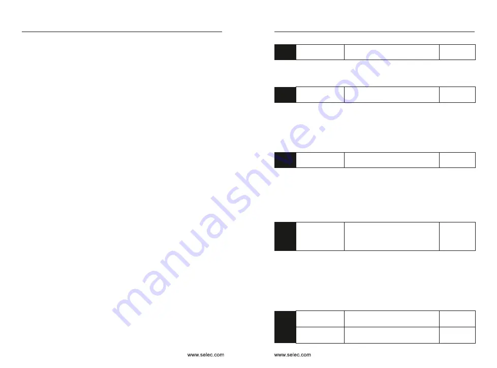
P0-08
0.00Hz
〜
Maximum frequency
(
P0-10
)
Preset frequency
When the frequency source is selected as digital setting or terminal
UP/DOWN, the function code value is the initial value of the frequency digital
setting of the inverter.
Default
:
0
P0-09
0: Same direction
1: Reverse direction
Rotation direction
It is used to change the running direction of the motor, which is equivalent
to adjusting any two lines of motor U, V and W to change the direction of the
motor.
Note: After the parameters are initialized, the motor running direction will
return to the original state. For the occasion where it is strictly prohibited to
change the motor steering, use it with caution.
Default
:
50.00Hz
P0-10
50.00Hz
〜
500.00Hz
Maximum
frequency
When P0-22=2, the frequency resolution is 0.01Hz, and the setting range of
P0-10 is 50.0Hz~500.0Hz.
It is used to set the corresponding value of 100.0% for analog input, pulse
input, multi-segment command, etc. as the frequency source.
When P0-22=1, the frequency resolution is 0.1Hz, and the setting range of
P0-10 is 50.0Hz~3200.0Hz;
Default
:
0
P0-11
0: Set by P0-12 1: AI1
2: AI2 3: AI3
4: Pulse setting
5: Communication setting
Source of
frequency
upper limit
Define the source of the upper limit frequency. When the upper limit
frequency is set with the analog input, 100% of the analog input setting
corresponds to P0-12.
(For example, when the torque control mode is adopted in the winding control
site, the upper limit frequency can be set by analog to avoid the “speeding”
phenomenon of material disconnection. When the inverter runs to the upper
limit frequency value, the inverter keeps running at the upper limit frequency.)
Default
:
50.00Hz
P0-12
Frequency lower limit P0-14 ~
maximum frequency P0-10
Frequency upper
limit
Default
:
0.00Hz
P0-13
0.00Hz to maximum frequency
P0-10
Frequency upper
limit offset
Chapter 6
Chapter 6


