Manual revision 001
Section 2: Description of SBE 39
plus
-IM
SBE 39
plus
-IM
17
Mooring Cable and Wiring Requirements
The standard 39
plus
-IM can mechanically accommodate mooring cables up to
16 mm (0.63 inches) in diameter. Clamps for specific diameters are available,
or can be supplied on a custom basis. Suitable mooring cables use steel wire
rope with a polypropylene or polyethylene-insulating jacket. The system
operates without data errors using up to 10,500 meters of 3 mm (0.12 inches)
or larger cable.
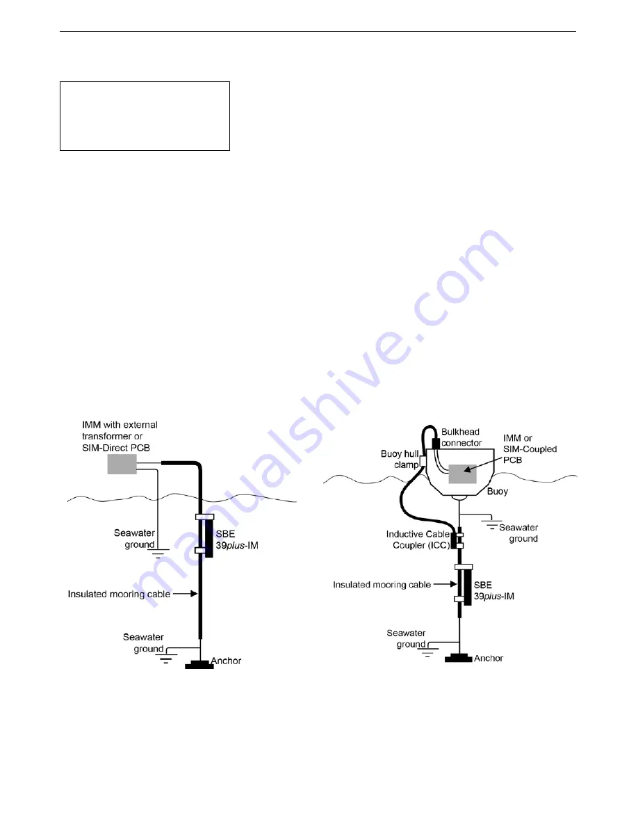
The mooring cable must provide connection to seawater ground below the
deepest IM instrument. Terminating the wire with a metallic eye or clevis
readily provides this connection.
The mooring cable must also provide for connection to the IMM or SIM.
•
In a direct connection (typical cable-to-shore applications), the bottom end
of the wire is grounded to seawater, and the top end remains insulated to
the connection to the IMM or SIM. A second wire from the IMM or SIM
connects to seawater ground, completing the circuit.
•
In typical surface buoys it is often preferable to connect the jacketed
mooring wire to the buoy with a length of chain, grounding the jacketed
wire to seawater at each end. An Inductive Cable Coupler (ICC) connects
the IMM or SIM to the jacketed wire above the uppermost IM instrument
and below the point where the wire is grounded.
Note:
For wiring, see applicable document:
•
IMM manual.
OR
•
Appendix III: SIM Hookup and
Configuration
.
Connection with
Inductive Cable Coupler (ICC)
Direct Connection


