17/90
User manual SCAIME:
NU-Soft-eNod4F-E-0716_235704-C.doc
5
CANOPEN
5.1
Physical interface
eNod4
is equipped with a CAN 2.0A compatible interface supporting
CANopen® communication protocol
. The device
can be connected to a CAN bus using
CANH
and
CANL
connections. A REF pin can also be connected. Supported baud
rates are 50000, 125000, 250000, 500000 and 1000000.
For a complete description of the recommendations about
eNod4
CAN connexion, please refer to documentation
“characteristics and functioning”
.
5.2
LED CANopen
The subsequent table describes the meaning of the LEDs for the CAN:
Color
State
Meaning
Red
Single Flash
At least one of the error counters of the CAN controller has reached or
exceed the warning level (too many error frame)
Double Flash
A guard event (NMT-slave or NMT-master) or a heartbeat event
(heartbeat consumer) has occurred
On
The CAN controller is bus off
Flash
Self-test: while the device is performing its power up testing, the LED
shall be flashing red
Green
Blinking
The device is in state PRE OPERATIONAL
Single Flash
The device is in state STOPPED
On
The device is in state OPERATIONAL
5.3
Frame format
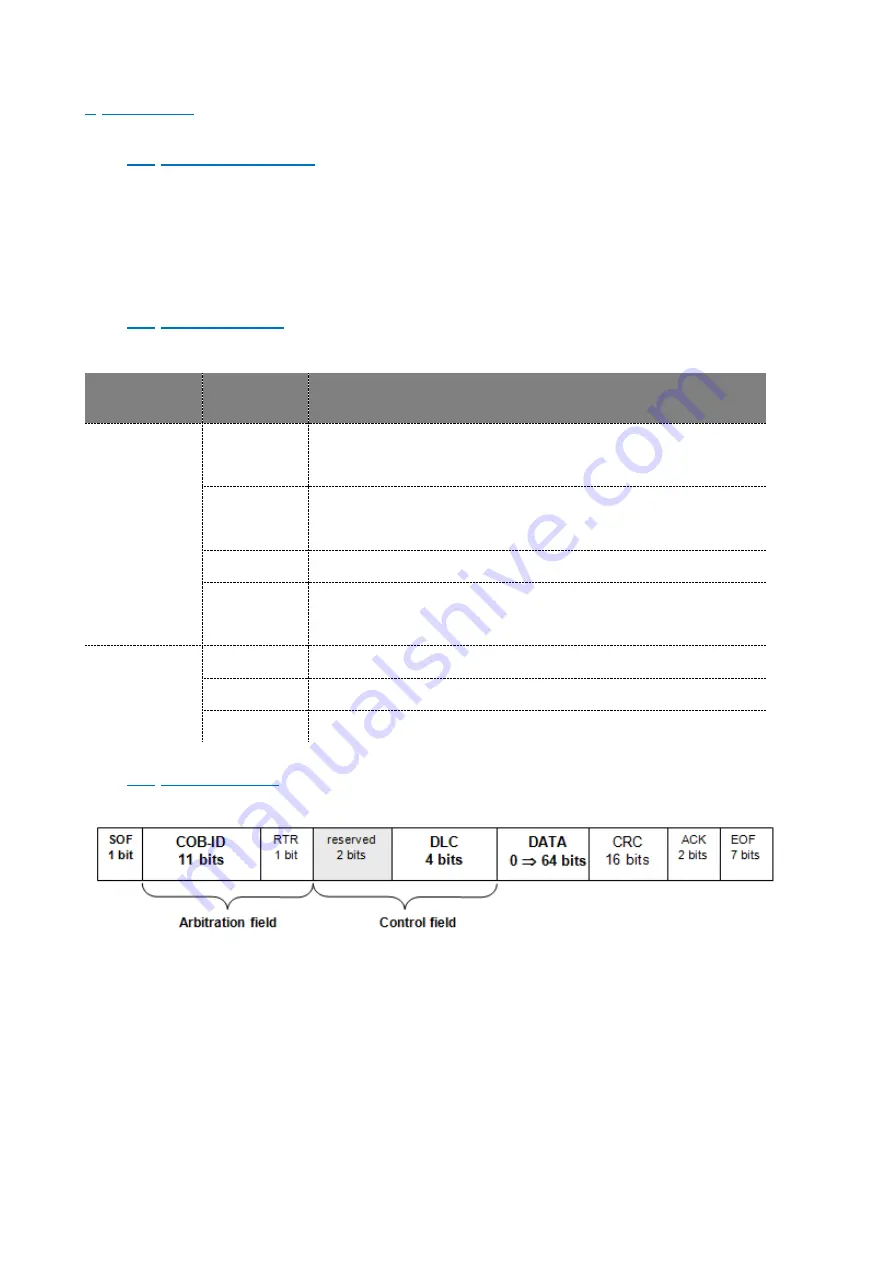
Every data frame sent on the CAN bus has the following structure:
-
Start of frame (SOF) : 1 bit
The beginning of a request or a data frame is indicated by the transmission of one
dominant bit.
-
Arbitration field : 12 bits
This field contains the message COB-ID on 11 bits and the RTR bit, dominant for data
frames and recessive for remote frames.
-
Control field : 6 bits
The first two bits are reserved and must be transmitted as dominant. The four remaining bits encode the
size of the transmitted data in bytes. This is called
«Data length code» (DLC)
with
0
DLC
8
.


