“1
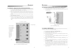
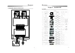
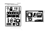
Chapter 7. PRODUCTS DRAWINGS
B=BLACK, W=WHITE, R=RED, G=GREEN, [S]=SHIELD
Solenoid Valve
(SV-20)
B
W
R G
INDICATOR
(FM-80B)
PW-
PW+
MT-
MT+
Auto-Pilot
DISPLAY
(SAS-70)
Black : (-)
White : (+)
POWER(DC 24V)
3P=8M
A-06
(FS-80B)
Cylinder
A-02
3P(S)=12M
RUDDER FEEDBACK
4P=5M
GPS Plotter
4P(S)=6M
A-10
A-05
A-03
2P(S)=6M
Auto Pilot - Control Unit(SAS-70C)
10P(S)=10M
6
P
(S
)=
1
2
M
A
-
0
4
COMPASS(ES-95)
2
P
(S
)=
5
M
12P(S)=4M/12M
7P(S)=5M
A-08
A-01
REMOTE ADAPTER(SAS-70A)
A-09
ELEC-LEVER
(SM-975A)
OPTION
S
W
IT
C
H
A
-
0
7
RC-30A(OPTION)
REMOTE CONTROL
RC-10A
5.5㎟ 3M
A-11
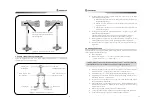
Connect black and white of solenoid valve in reverse in case of operation of the rudder
Connect red and white of transmitter in reverse in case of operation of the Rudder Angle Indicator
“2
1
5
8
159
1
4
2
±
0
.5
1
3
3
+
1
-
0
.5
100
±0.5
4
-
?
5
(M
4)
148
+1
-0.5
1
7
0
Y


