41
Chapter 2. System Installation
2.1 Installation of Control Cables
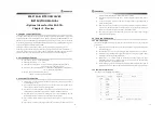
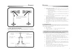
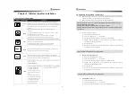
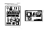
Configuration of link cables for engine governor and clutch is as follow picture.
It should not be installed at the place with heavy vibration, high temperature and
exposed to rainwater or sea water.
The diameter of control cable has to be less than 50Cm and has not to be installed as
being bent.
When the engine is connected to manual lever and manual lever to electronic lever
through the cable, the above connections has to be done without backlash
Either switching to forward / maximum speed position by pulling control cable or by
pushing the control cable which is connected to electronic lever, there will be no
problems of operating. So control cable can be connected as above picture.
Control cable
< Figure 2-1. Drawing of Control cable installation >
Engine Clutch
Engine Governor
Manual lever
Govenor
Clutch
Clutch lever
Governor lever
Electronic lever
WARNING Governor can not be controlled minutely if there is too much backlash on the
connections
WARNING Initial setting that switching to forward / maximum speed position by pulling
the control cable should be done after installation
42
2.2 How to connect Control cables
E
5 C
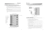
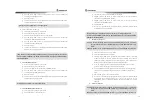
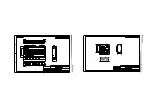
< Figure 2-2. Connecting control cable >
When open the lid of electronic lever, you will see two levers as above picture. The left
one is clutch lever and the right one is governor lever.
When dismantle the manual lever, you will see the control cables that are connected to
engine clutch and governor. There is also another connection points on manual lever for
control cables that can be connected to electronic lever. (control cable will be along with
main unit when it is released)
After assembling the manual lever, put the clutch and the governor of manual lever on
middle point of the lever.
Mount a cable link-pin "②" on the end of control cable that is connected to manual and
tighten up a screw.
Put the levers "①" on middle point and connect the clutch cable and governor cable to
the levers respectively. ( connect "①" with "②" in the above picture.)
Fix the cable through the cable fixing plate"④"
Check whether the electronic lever is working properly according to the motions of the
clutch and governor lever.
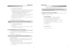
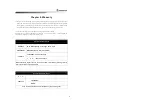
Mount a cable fixing pin on the outside of electronic lever as the below picture If there is
any difference between moving space of manual lever and electronic lever.
Clutch lever
Governor lever
Clutch cable Diagram
Governor cable Diagram
Cable fix pin
Cable fix pin
Cable fixing plate
Cable fixing plate
Cable
Cable
(Connected to manual clutch lever)
(Connected to manual Governor lever)
1
1
2
2
3
3
4
4

