25
Rudder Feedback
Conneting rod
PORT Cylinder
Tiller
STBD Cylinder
A
T
P
B
Helm
T
P
T
P
B
A
Oil Tank
Oil Pump
B
T
P
A
Solenoid Valve
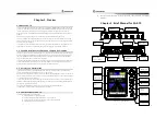
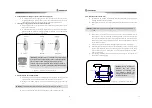
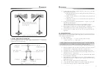
< Figure “-3. Piping diagram after installation for Solenoid valve >
6.4 Piping diagram at a cylinder type
When the oil-pressure is given in the pipes connected to the solenoid, the Left(B) pipe is the pipe to
which the ship direction turns left while the Right(A) pipe is the pipe to which the ship direction turns
right. So it should be piped as shown below.
Rudder Feedback
Conneting rod
Cylinder
Tiller
A
B
Solenoid Valve A
Solenoid Valve B
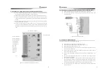
< Figure “-4. (Left) Piping diagram at a cylinder type >
2“
Conneting rod
Cylinder
Tiller
B
A
Solenoid Valve B
Solenoid Valve A
Rudder Feedback
< Figure “-5. (Right) Piping diagram at a cylinder type >


