35
“
System info.
Enable to view of system information
”
Update
Only available function for registered engineers
8
Initial setup
Return all set values to an initial factory status
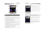
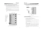
8.1.6 Option, Warning, Measurement
[ MENU ] [ OPTION ] [ WARNING ]
[ MEASUREMENT ]
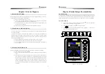
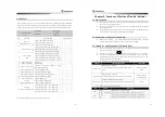
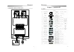
< Figure 8-“. Option, measurement, warning >
NO
MENU
FUNCTION
1
3. Option
Set offset for standard time, rotating angles on rotate mode (5°~30°, 5°step), Set
if Weathercock, gauge, tank, exercise screen are displayed
2
4.Warning
Set range of warning or make ON/OFF. Warning icon is activated in setting each
warning or making ON.
3 5.Measurement
Set how to express the measurement (unit) for data showing in navigation
screen.
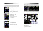
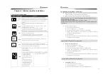
8.1.7 Self test result
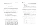
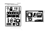
< Figure 8-”. Self test >
“.Self Test
MNU
3“
NO
MENU
FUNCTION
1
System
Monitoring
It consists of 2 screens to supervise basic data input by this pilot system and
other information both. Especially there are Rudder, Remote, Compass X,
Compass Y, Compass R, Power Voltage with A/D values. When dialing a DIAL to
right direction, possible to view other information.
2
Memory Test
Indicated normal / error status after checking out inter memory for control unit
or indicator device.
3
Key Test
Check out status of functional keys SAS-”0.
Valuable keys are [Left dial], [Right Dial], [Confirm], [ESC], [MENU], [ROTATE],
[SCREEN], [MANUAL], [MODE]. Press [ESC] button more than 3 times to return
a previous menu.
4
Compass
Revised values
Capable to view values of [Ship calibrate] and [45° setup] set by SAS-”0.
The calibrate values means max value and minimum value among A/D values
input thru X-channel, Y-channel during rotation for ship calibration.
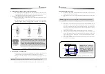
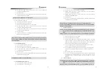
8.1.8 Adjustment for Solenoid valve
Not related to security issue in direct and if the adjustment is wrong set, the efficiency of unit is
decreased so that it should be adjusted after installed circuit of oil pressure / electric circuit.
SV - 20
① After completely installed, put the steering controller onto a neutral position and
select [REMOTE] mode among steering modes. Then, if the rudder is moving to
end-left or end-right direction, switch black cable and white cable of solenoid.
② Put the steering controller onto end-left (-40°) seeing the movement of rudder and
after awaiting for reaching to end-left point, roll the steering controller to end-right
(+40°) position seeing a clock rapidly.
③ Check the time that rudder is moving from end-left to end-right position and control
the valve oil-volume controller to reach for about 10 ~ 15 seconds.
③
As proceeding the above step of ② and ③ phases, adjust the time (time of moving
from end-left to end-right and of moving from end-right to end-left) to reach for
about 10 ~ 15 seconds continuously. (When the time of moving from end-left to
end-right position is adjusted the time of moving from end-right to end-left
position is same adjusted.)
WARNING If solenoid is operated in conditions of closing status or lower controlling status
for oil volume of the controller, the heats take place in the pressure oil.
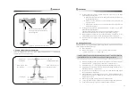
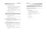
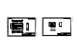
< Figure 8-8. SV – 20 Solenoid valve >
REF In case of adjusting the oil volume, speed
adjustment of left-right / right-left direction should be
done separately due to the controllers are located each
other in SV-20. ( “ “ ……… Controller for oil volume )


