21
5.3.2 Installation for Compass sensor (Electronic Compass)
To install direction sensor, keeping it away from the place where not only there is
magnetism effecting to sensor performance but also solenoid valve, motor or electric
cable. The most efficient place to install is lower part of hull and center of hull.
※
Top bridge is strongly recommendable for installation position.
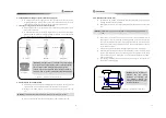
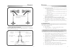
Install to follow white line on the side of direction sensor. This marked direction have to
face direction of the bow.
To install direction sensor, fix the sensor bracket to hull or hull structure and sensors
direction should be installed as following figures. Minor direction error can be corrected
by magnetic difference correcting at initial setting.
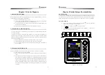
5.3.3. Installation for Solenoid valve
Install solenoid valve close to manual steering wheel. It makes easy to do piping work for
hydraulic system. If it is not possible, install it near at oil pump or other places.
Making 4 holes in 8mm diameter at the position of installation and fix it with bolt and
nut.
Install it in easy position to control the oil regulator located in solenoid valve unit.
< Figure 5-2. Installation for Compass sensor >
E.Compass
Heading
Heading
Heading
E.compass
E.compass
GOOD
GREAT
WRONG
WARNING]
:
Install Electronic coil horizontally. Otherwise it can cause poor function.
WARNING direction sensor is so sensitive that it easily affected
by magnetic force nearby during the automatic steering navigation
that can cause a sudden turning of ship. So to prevent this
situation, magnetic force generated device should be isolated, at
least 50cm, from our product (all kind of magnetic classified tools).
E.compass
22
5.3.4 Installation for Transmitter
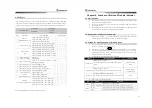
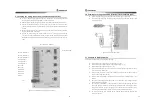
Any directions are available for installation direction of transmitter (angle sensor) but
following instructions are recommended.
Make 4 holes by 9mm dia. at installation table and fix transmitter onto it with bolts and
nuts.
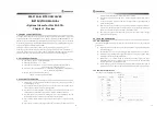
Make a hole or fix the bolt (size : 8mm dia/lenth 30mm) at the same distance (refer to
below figure V1) with transmitter side' connecting rod from the center of the tiller and
link it with connecting rod, then tiller's steering angle and transmitter's steering angle will
become same. If user wants its angle to be accurate, adjust V1 with adjusting screw until
V1 and V2 become same.
Install connecting rod horizontally by adjusting height of transmitter (angle sensor).
Install steering wheel angle to become central position. When tiller is located to central
position. (After installation, adjust it with adjusting screws (H2 interval) maximum adjust
range of connecting rod is within 20mm, if you need more adjustment than 20mm,
replace it with others.)
After finishing installation, the distance between H1 and H2 have to be equivalent (V1
and V2 also) as followings figure.
V
2
V
1
Rudder Feedback
Conneting rod
PORT Cylinder
Tiller
STBD Cylinder
H2
H1
WARNING Avoid installing places where exposed to a strong vibration, high temperature,
sea
< Figure 5-3. Installation for transmitter >
WARNING Wrong positioning of
feedback
unit
and
wrong
installation of connecting rod
cause difference between real
steering angle and indicated signal
of steering controller.


