23
Chapter 6. Hydraulic Piping
6.1 Before Hydraulic piping
Refer to the Piping Diagram to ensure that there is nothing wrong about the piping.
Connect carefully the joints of the copper pipe and each part to the direction of the sleeve.
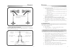
In cutting the copper tube, use a pipe cutter only and cut the up-and-down at a right angle.
Fix the copper pipe with a proper press-button device.
After completing the piping, clean the surroundings of the pipes and disassemble the linked part
and brush off the inner copper pipe.
After finishing brushing, reassemble it and make some air evacuation according to the manual of
the steering wheel.
Oil filter should be installed in the oil tank. (By placing a permanent magnet inside the oil tank, the
iron substance can be removed.)
Clean the oil tank and the pipes. Then change the oil with new replacement oil.
When piping with rubber oil hoses, the ends of the hoses should be firmly connected.
Complete all the procedures and connect it to the steering wheel controller (it refers to "electrical
wiring".) and start the engine and check if the tiller works normally through turning the adjustor of
the remote control. If it moves to the opposite direction, correct it for SAS-” use of SOLENOID
electrical wiring. (This is connected to the terminal plate) and connect it to the properly working
spot.
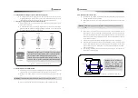
In installing oil-pressure pipes, if there is any part that contacts against the hull, tighten it firmly by
using such fasteners as PCV belt. In case of the copper pipe, wrap it with rubber and then tighten it.
The followings are the abbreviations used in the pipe distribution diagram.
T : This refers to the pipe connecting part which is linked to the oil tank.
P : This refers to the pipe connecting part which is linked to the oil pump.
A : Also expressed 'L' (the opitrol of the manual steering wheel), this refers to the pipe connecting
part where the tiller moves clockwise (Ship will turn left) when the oil pressure is made in A pipe.
B : Also expressed 'R' (the opitrol of the manual steering wheel), this refers to the pipe connecting
part where the tiller moves counter-clockwise (Ship will turn right) when the oil pressure is made
in B pipe.
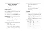
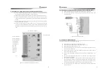
6.2 Piping diagram before installation for Solenoid valve
This instruction manual explains about the installation procedures, based on those ships that are
equipped with the following oil-pressure circuit. If you have any questions on other oil pressure
systems, contact any specialist for more help.
After the installation of the oil-pressure pipes and electrical circuits, it is sometimes
required to adjust the solenoid oil pressure controller. For example, when the rudder is
controlled by solenoid under the remote mode, the compass mode and the plotter
WARNING Cutting with a saw will create any chips that cause the breakdown.
REF Fix it at every 1m in case of straight line and at every 30Cm in case of curve.
WARNING A is also expressed as 'R' and B is 'L' in the opitrol pipe of the manual steering.
24
steering mode, you need to adjust it if the rudder movement is too speedy or too slow.
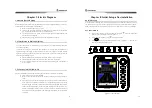
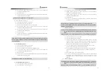
The oil controller is installed in the bottom part of the solenoid valve.
A
T
P
B
Helm
T
P
T
P
B
A
Oil Tank
Oil Pump
Rudder Feedback
Conneting rod
PORT Cylinder
Tiller
STBD Cylinder
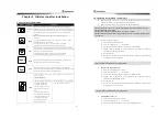
6.3 Piping diagram after installation for Solenoid valve
Refer to the following procedures to connect the solenoid valve in the existing oil pressure pipes.
Separate "P" pipe from the oil pump. (The "P" pipe is linked to the opitrol)
Connect "P" of the oil pump and the oil controller (Relief valve). Then connect "P" of the
solenoid valve to the opposite side where "P" of the oil pump "P" is set in.
Connect "T" of the solenoid to "P" of the opitrol.
Separate the pipes linked between "A(R)" of the opitrol and "A" of the left side cylinder.
Use T-type joint to connect "A" of the solenoid valve, "A(R)" of the opitrol and "A" of the
left side cylinder together.
Separate the pipes linked between "B(L)" of the opitrol and "B" of the right side cylinder.
Use T-type joint to connect "B" of the solenoid valve, "B(L)" of the opitrol and "B" of the
left side cylinder together.
Use T-type joint to connect "T" of the oil tank, the oil controller and "T" of the opitrol
together.
< Figure “-2. Piping diagram before installation for Solenoid valve >


