19
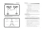
4.15 FUNCTIONS OF REMOTE CONTROLLER
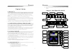
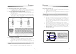
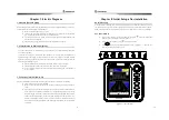
4.15.1 Remote Controller of RC-10A
< Figure 4-”. Remote Controller of RC-10A >
Shows current heading bearings of own ship.
It is Remote Steering controller and rudder is located in
a center at center position and it can be adjusted with
40° to left and right direction. It should be put at a
center in Compass, Plotter auto Steering mode.
20
Chapter 5. System Installation
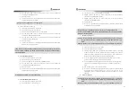
5.1 BEFORE INSTALLATION
Avoid mounting as follows
Exposed to rain or sea water
Difficult places to check, to repair and to plumb.
Exposed to direct rays and hot temperature
Exposed to severe vibration like near by engine
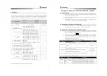
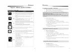
5.2 CONFIGURATION OF SYSTEM
The system is configured as followings.
ITEM
MODEL
Q
’
TY
REMARK
Display
SAS-”0
1 EA
Controller
SAS-”0C
1 EA
Remote Adapter
SAS-”0A
1 EA
Solenoid Valve
SV-20
1 EA
Direction Sensor
ES-95
1 EA
Transmitter
FS-80B
1 EA
Rudder Angle
Indicator
FM-80B
1 EA
Remote
Controller
RC-10A(OPTION
RC-30A)
1 EA
Installation
material
-
1 SET
Ref. PACKING LIST
Engine control
SM-9”5A
1 SET
OPTION
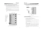
5.3 INSTALLATION FOR AUTO PILOT
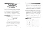
5.3.1 Installation for display units
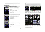
< Figure 5-1. Installation for display units >
Select a spot for display installation and fix an installation bar with screws
.
Fix the display onto an installation bar
Install it for easy operation in a spot not affecting to ship navigation
Refer to Chapter 7. for detail measurement


