3”
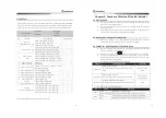
8.2 Self Test
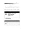
The self testing value can vary each time, and the numbers can be used by specialists in SAMYUNG
to figure out the system performance according to diagnosis condition; therefore, when any trouble
cannot be shot out, and sent this form to A/S Center, it will be facilitated the A/S procedure faster.
Vessel Name
Installed date
Test date
SELF TEST REPORT
Serial number
Inspector
NO
TEST LIST
TEST CONDITION
RESULT VALUE
Transmit -40°, Rudder value (A/D)
( )
Transmit -0°, Rudder value (A/D)
( )
1
Self Test -
System Monitoring - (1)
Tr40°, Rudder value (A/D)
( )
Remote Controller -40°, Remote value (A/D) ( )
Remote Controller -0°, Remote value (A/D) ( )
2
Same as above (2)
Remote Cont40°, Remote value (A/D) ( )
Value of Heading 0°, Compass(X / Y) value
( / )
Value of Heading 90°, Compass(X / Y) value
( / )
Value of Heading 180°, Compass(X / Y) value ( / )
3
Same as above
(3~4)
Value of Heading 2”0°, Compass(X / Y) value ( / )
4
Same as above (5)
Compass R:
( )
5
Same as above (“)
Power Voltage:
( )
“
Same as above (”~10)
Compass variation/the ratio/wave height
ratio/Rudder Steering ratio:
( / / / )
”
Same as above (11~12) Rudder Gauge Max / Min:
( / )
8
Same as above (13~15) Rudder Left / Middle / Right:
( / / )
9
Same as above (1“~1”) Rudder sensitivity / hydro property :
( / )
10 Same as above (18~20) Remote Left / Middle / Right:
( / / )
11
Same as above (21)
Rapid rotation angle:
( )
Compass X(Min), X(Max) value
( / )
12
Self Test -
Compass Adjust Values Compass Y(Min), Y(Max) value
( / )
45° revised value: 000° / 045° ( 000 / 045)
( / )
45° revised value: 090° / 135° ( 090 / 135)
( / )
45° revised value: 180° / 225° ( 180 / 225)
( / )
13
Self Test -
Compass Adjust Values
45° revised value: 2”0° / 315° ( 2”0 / 315)
( / )
After installed this SAS-”0, the installed man must fill it out.
38
Chapter 9. Funtions of Alert and Trouble indicator
9.1 Alert Function
SAS-”0 provide information as such out of route, no heading signal, low power voltage
alert, waypoint, auto navigate alert etc.
On marking checking mark in LCD screen, the alert is working and On no marking, the
alert is not working.
This function works under electric compass / chart plotter based auto steering mode, but
under manual and remote mode, this function will be disabled.
9.2 Remote Alert Funtion for adjustment
Under electric compass / chart plotter operation based steering mode, if turns the
control knob more than 5 degrees away from neutral, the alarm beeps.
9.3 Funtion for indicating troubles (Operate Error)
SAS-”0 has function to check it the unit has errors. During operation, the alert take place
and mark it in a display if the unit has errors.
When the alert is ringing, press
button to stop the sound and it is rechecking.
If it has errors, delete the reason of errors and make to operate it again. (If you don’t
delete the defective reason and you operate it continuously, it can be made more serious
errors for over capacity of oil pressure.
The types of errors and the contents are as followings.
ERRORS
TRAOUBLESHOOTING
CONDITIONS
Rudder Error
Malfunctioning on Rudder
For solution, please check the solenoid valve or angle
sensor
Remote, Compass,
Plotter
Compass Error
Malfunctioning on Compass
For solution, please check out the compass connection
Manual, Remote,
Compass, Plotter
Plotter Error
Connection problem with chart plotter
For solution, please check the connection status of plotter
Plotter
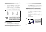
Status of LED at controller of SAS-”0C
LED
STATUS
FUNCTION
Green
Meaning that it is well working
POWER
Green / Red (on/off)
Meaning that tele-error of CAN, compass error and so on
Green
Meaning that the solenoid valve is working to left direction
VALVE
Red
Meaning that the solenoid valve is working to right direction
ESC


