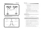
2”
Chapter 7. Electric Diagram
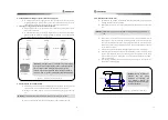
7.1 Before hydraulic piping
Before setting the wires, please abide by the following instructions. Improper handling may cause any
serious electric shocks or damages to the equipment.
Make sure that the power supply is closed.
Check out DC 24V of the power terminal (Black, White, G). Never connect the opposite
way. The polarities of power are white for (+) and black for (-).
For linking the terminal box, confirm the terminal signal and the cable position and then,
work on the exact connection.
After completing piping, check the status of the terminal box once again.
7.2 Interference to Radio equipment
It is often vulnerable to the interferences of radios. Keep away the autopilot-related cables from
other cables if possible.
In case that the autopilot is interfered by radio equipment, for the most part, the interference is
expressed through the change of the bow direction. If there is any change of the bow direction
while any transmitting is made by any radios, it means the system is interfered. In order to avoid this,
please keep the followings in mind.
Keep the steering wheel, the direction sensor from antenna as far as possible.
Keep the autopilot-related cable from other radio cables as far as possible.
Do not install the steering wheel around the coax cables stretching from radio equipment
to their antennas.
7.3 Cautions in initial Power-On
Please be careful about the following instructions when the power is supplied for the first time.
Check if the pluming is correctly designed.
Make sure that the specifications of the equipment, including the battery voltage are
correct.
If the engine start is turned after turning on the power, there are some possibilities that a
drastic change or any abnormal malfunction may happen. When power on, it will make
the buzzer ringing, LCD display of the panel center will show the changed mode status in
current use (the selected mode). If it does not show anything even after the power is on,
the fuse is considered as broken. Find out the cause as fuses are installed at the back of
the main unit, each one for 3A and for 10A respectively. Then replace it with a spare fuse
if necessary.
28
Chapter 8. Initial Setup after installation
8.1 Initial setup
As the equipment s delivered from the factory, going through all the detailed adjustments, users are
not required to set up the most functions but the setup of functions as such solenoid valve, compass,
rudder, neutrality of remote, characteristic of oil pressure is required. The initial setup is as followings.
8.1.1 Power ON/OFF
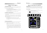
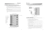
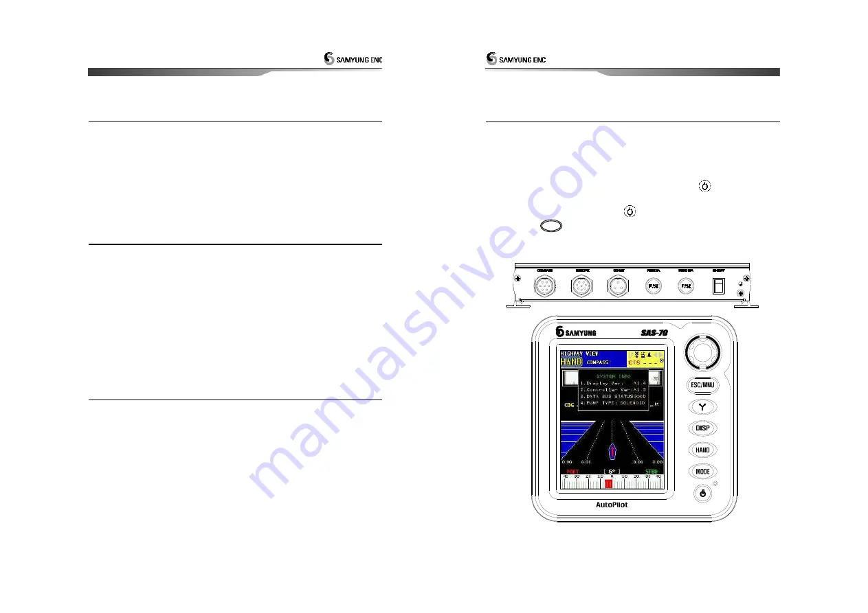
Turn on Power switch of control part (SAS-”0C) and press
button on display part
(SAS-”0). Then, the following LCD screen comes on.
To turn off power of display, press
button for 2 seconds.
Press
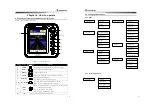
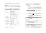
button, then the following figure as such < Figure 8-2. > comes on. The
user can set among categories on menu.
< Figure 8-1. Power ON/OFF >
MNU


