Circuit Description
Samsung Electronics
5-7
ENGINE CONTROLLER
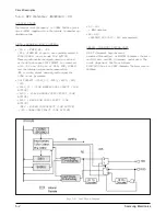
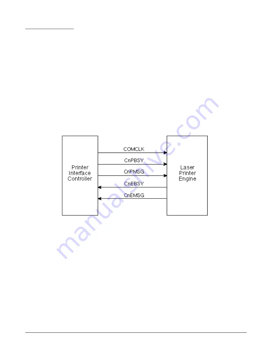
• Message Communication
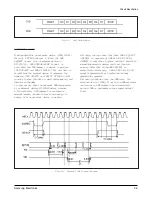
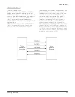
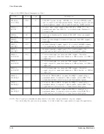
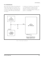
The print interface uses CnPMSG and CnEMSG to
transmit and receive 8-bit message, CnPBSY and
CnEBSY to indicate the direction of data transfer and
COMCLK to pace data transmissions. PIFC does not
employ handshaking, but asserts CnPBSY and
CnEBSY before the actual data transmission to
provide sufficient time for the logic to prepare for the
subsequent data.
COMCLK remains inactive until either CnPBSY or
CnEBSY is asserted and then goes through eight
periods for 8-bit data transmission or reception.
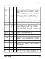
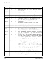
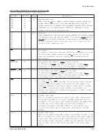
Three registers, TBR (Transmit Buffer Register), RBR
(Receive Buffer Register), are used for message
communication. The TBR and RBR contain the 8-bit
command to be transmitted to the printer engine
through the CnEMSG pin and the 8-bit engine
message received for the printer engine through the
Cnemsg pin, respectively. The CMOD contain a
transmit enable bit (TX) to make CnPSBY signal
active, a read-only status bit (RX) to indicate the
Cnebsy signal status and 5-bit prescaler value used to
generate COMCLK clock. In message reception, the
RX bit is cleared when a low-to-high transition occurs
on CnEBSY, and at the meantime an interrupt signal
INT_BUSY is posted to indicate that one-byte engine
message has been received by PIFC.
Содержание MSYS 5150
Страница 9: ...2 6 Samsung Electronics Specification Memo ...
Страница 16: ...3 26 Samsung Electronics Setup and Installing Memo ...
Страница 37: ...4 2 Samsung Electronics Theory of Operation ...
Страница 41: ...4 6 Samsung Electronics Memo Theory of Operation ...
Страница 116: ...Samsung Electronics 7 9 Maintenance Troubleshooting No Image ...
Страница 117: ...Samsung Electronics Maintenance Troubleshooting 7 10 ...
Страница 118: ...Samsung Electronics 7 11 Maintenance Troubleshooting All Black ...
Страница 119: ...7 12 Samsung Electronics Maintenance Troubleshooting Vertical White Line Band ...
Страница 120: ...Samsung Electronics 7 13 Maintenance Troubleshooting Dark Image ...
Страница 121: ...7 14 Samsung Electronics Maintenance Troubleshooting Background ...
Страница 122: ...Samsung Electronics 7 15 Maintenance Troubleshooting Ghost ...
Страница 123: ...7 16 Samsung Electronics Maintenance Troubleshooting Black Dot ...
Страница 124: ...Samsung Electronics 7 17 Maintenance Troubleshooting Horizontal Band ...
Страница 125: ...7 18 Samsung Electronics Maintenance Troubleshooting Irregular Density ...
Страница 126: ...Samsung Electronics 7 19 Maintenance Troubleshooting White Spot ...
Страница 127: ...7 20 Samsung Electronics Maintenance Troubleshooting Trembling at the End When OHP Printing ...
Страница 128: ...Samsung Electronics 7 21 Maintenance Troubleshooting Poor Fusing Grade ...
Страница 132: ...Samsung Electronics 7 25 Maintenance Troubleshooting No Power LCD NO display LED Off ...
Страница 133: ...Fuser Error 7 26 Samsung Electronics Maintenance Troubleshooting ...
Страница 134: ...Samsung Electronics 7 27 Maintenance Troubleshooting Paper Jam Mis feeding ...
Страница 135: ...7 28 Samsung Electronics Maintenance Troubleshooting Paper Jam Jam1 ...
Страница 136: ...Samsung Electronics Maintenance Troubleshooting 7 29 Engine Error ...
Страница 137: ...7 30 Samsung Electronics Maintenance Troubleshooting Memo ...
Страница 187: ...9 28 Samsung Electronics Electrical Parts List ...
Страница 189: ...11 Connection Diagram Samsung Electronics 11 1 ...
Страница 190: ...12 1 Main Circuit Diagram Samsung Electronics 12 1 12 Schematic Diagrams ...
Страница 191: ...Schematic Diagrams 12 2 Samsung Electronics Main Circuit Diagram ...
Страница 192: ...Main Circuit Diagram Samsung Electronics 12 3 Schematic Diagrams ...
Страница 193: ...Schematic Diagrams 12 4 Samsung Electronics Main Circuit Diagram ...
Страница 194: ...Main Circuit Diagram Samsung Electronics 12 5 Schematic Diagrams ...
Страница 195: ...Schematic Diagrams 12 6 Samsung Electronics Main Circuit Diagram ...
Страница 196: ...Main Circuit Diagram Samsung Electronics 12 7 Schematic Diagrams ...
Страница 200: ...12 3 Sensors Circuit Diagram Samsung Electronics 12 11 Schematic Diagrams ...
Страница 201: ...Schematic Diagrams 12 12 Samsung Electronics 12 4 Switch Circuit Diagram ...
Страница 202: ...Samsung Electronics 12 13 Schematic Diagrams 12 5 Joint Circuit Diagram ...
Страница 203: ...Schematic Diagrams 12 14 Samsung Electronics 12 6 OPE Circuit Diagram IF Active HIGH Logic IF Active LOW Logic ...
Страница 204: ...Samsung Electronics 12 15 Schematic Diagrams 12 7 PTL Circuit Diagram ...
Страница 205: ...Schematic Diagrams 12 16 Samsung Electronics 12 8 SCAN Circuit Diagram ...
Страница 206: ...Samsung Electronics 12 17 Schematic Diagrams 12 9 Engin Circuit Diagram ...
Страница 207: ...Schematic Diagrams 12 18 Samsung Electronics Engin Circuit Diagram ...
Страница 208: ...Samsung Electronics 12 19 Schematic Diagrams 12 10 LIU Circuit Diagram ...
Страница 210: ... Samsung Electronics Co Ltd Mar 1999 Printed in Korea P N JC68 00097A Rev 1 00 ELECTRONICS ...


