Samsung Electronics
5-27
5-4 LIU PBA
5-4-1 Summary
LIU(Line Interface Unit) circuit added only to
Msys 5200,
Msys 5150, SF-5800, SF-5800P i
s
controlled by the main circuit.
It monitors telephone line and helps interface between
the system and the telephone line. It uses
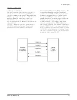
1-LIU(STI9510) to control the whole LIU,
MODEM/LINE INTERFACE, RING SIGNAL
DETECTOR, DIALER, LINE CURRENT
DETECTOR, and SERIAL INTERFACE.
5-4-2 Modem/Line Interface
This is the path through which transmitted and
received data of modem is put in and out.
• CML1 Relay: It divides telephone line into
external telephone and fax.
• U3-3 TIT(Transformer Input from Transformer):
This single ended input receives image signals fro m
modem through transformer T2 and
transmits them on telephone line.
• U3-40 ROT(Receive Output Transformer): This
output transformer receives signals on telephone
line and delivers them to modem through
transformer T1. It has AC impedance of 10Kohm or
over.
• AC impedance: Normal operation range of
U3(STI9510) is from 15mA to 100mA. DC
characteristics depend on the voltage of U3-37
LI(Line Input) terminal and the voltage of
resistance R48 between U3-37 LI(Line Input)
terminal and U3-39 LS terminal.
5-4-3 Ring Signal Detector
• U3-28(MO) terminals are ring signal output
terminals. Q4 and Q5 put out ring signals and drive
Piezzo, but Msys 5200,
Msys 5150, SF-5800,
SF-5800P does not use Piezzo. It has only the
functions related to ring detection such as driving
the photocoupler of U4 and delivering ring signals
to MFP
controller of the main.
5-4-4 Dialer
5-4-4-1. MF DIAL
• Default mode it is set in DP.
You can change it to
MF mode by control of MFP controller.
• MF signal can be measured at (tone level of low
group: typical - 14dBm) U3-4 MFO(DTMF
Generator Output). The signal is adjustable by R40,
R41 and C29. The adjusted signal enters U3-9 MFI
(DTMF Amplifier Input) and is amplified to be
transmitted on telephone line.
• U3-39 LS(Line Current Sense Input) terminals show
the final signals transmitted to telephone line.
5-4-4-2. DP DIAL
• If U3-2(DMS) is made Vcc by R42, it is set at 33:67
D P signal. If it is made Vss by R43, it is set at DP
signal. This product is set at DP signal.
• D P signal is made by U3-27(DPn) terminals. This
signal turns on/off Q1. The signal made at that time
turns on/off Q2, which interrupts DC
current on telephone line and puts out pulse
signal on telephone line.
• U3-35 CS terminals : It makes Make Resistance by
shorting telephone line with Vss during Make
period of DP dial.
5-4-5 Line Current Detector
• When CML1 relay connects telephone line, U3
(STI9510) of LIU board and MFP controller of the
main board (U16) start communication through
U A RT. U3 of LIU board sends signal that includes
information of line current value, whenever it
receives orders or data from U16 of the main board.
Circuit Description
Содержание MSYS 5150
Страница 9: ...2 6 Samsung Electronics Specification Memo ...
Страница 16: ...3 26 Samsung Electronics Setup and Installing Memo ...
Страница 37: ...4 2 Samsung Electronics Theory of Operation ...
Страница 41: ...4 6 Samsung Electronics Memo Theory of Operation ...
Страница 116: ...Samsung Electronics 7 9 Maintenance Troubleshooting No Image ...
Страница 117: ...Samsung Electronics Maintenance Troubleshooting 7 10 ...
Страница 118: ...Samsung Electronics 7 11 Maintenance Troubleshooting All Black ...
Страница 119: ...7 12 Samsung Electronics Maintenance Troubleshooting Vertical White Line Band ...
Страница 120: ...Samsung Electronics 7 13 Maintenance Troubleshooting Dark Image ...
Страница 121: ...7 14 Samsung Electronics Maintenance Troubleshooting Background ...
Страница 122: ...Samsung Electronics 7 15 Maintenance Troubleshooting Ghost ...
Страница 123: ...7 16 Samsung Electronics Maintenance Troubleshooting Black Dot ...
Страница 124: ...Samsung Electronics 7 17 Maintenance Troubleshooting Horizontal Band ...
Страница 125: ...7 18 Samsung Electronics Maintenance Troubleshooting Irregular Density ...
Страница 126: ...Samsung Electronics 7 19 Maintenance Troubleshooting White Spot ...
Страница 127: ...7 20 Samsung Electronics Maintenance Troubleshooting Trembling at the End When OHP Printing ...
Страница 128: ...Samsung Electronics 7 21 Maintenance Troubleshooting Poor Fusing Grade ...
Страница 132: ...Samsung Electronics 7 25 Maintenance Troubleshooting No Power LCD NO display LED Off ...
Страница 133: ...Fuser Error 7 26 Samsung Electronics Maintenance Troubleshooting ...
Страница 134: ...Samsung Electronics 7 27 Maintenance Troubleshooting Paper Jam Mis feeding ...
Страница 135: ...7 28 Samsung Electronics Maintenance Troubleshooting Paper Jam Jam1 ...
Страница 136: ...Samsung Electronics Maintenance Troubleshooting 7 29 Engine Error ...
Страница 137: ...7 30 Samsung Electronics Maintenance Troubleshooting Memo ...
Страница 187: ...9 28 Samsung Electronics Electrical Parts List ...
Страница 189: ...11 Connection Diagram Samsung Electronics 11 1 ...
Страница 190: ...12 1 Main Circuit Diagram Samsung Electronics 12 1 12 Schematic Diagrams ...
Страница 191: ...Schematic Diagrams 12 2 Samsung Electronics Main Circuit Diagram ...
Страница 192: ...Main Circuit Diagram Samsung Electronics 12 3 Schematic Diagrams ...
Страница 193: ...Schematic Diagrams 12 4 Samsung Electronics Main Circuit Diagram ...
Страница 194: ...Main Circuit Diagram Samsung Electronics 12 5 Schematic Diagrams ...
Страница 195: ...Schematic Diagrams 12 6 Samsung Electronics Main Circuit Diagram ...
Страница 196: ...Main Circuit Diagram Samsung Electronics 12 7 Schematic Diagrams ...
Страница 200: ...12 3 Sensors Circuit Diagram Samsung Electronics 12 11 Schematic Diagrams ...
Страница 201: ...Schematic Diagrams 12 12 Samsung Electronics 12 4 Switch Circuit Diagram ...
Страница 202: ...Samsung Electronics 12 13 Schematic Diagrams 12 5 Joint Circuit Diagram ...
Страница 203: ...Schematic Diagrams 12 14 Samsung Electronics 12 6 OPE Circuit Diagram IF Active HIGH Logic IF Active LOW Logic ...
Страница 204: ...Samsung Electronics 12 15 Schematic Diagrams 12 7 PTL Circuit Diagram ...
Страница 205: ...Schematic Diagrams 12 16 Samsung Electronics 12 8 SCAN Circuit Diagram ...
Страница 206: ...Samsung Electronics 12 17 Schematic Diagrams 12 9 Engin Circuit Diagram ...
Страница 207: ...Schematic Diagrams 12 18 Samsung Electronics Engin Circuit Diagram ...
Страница 208: ...Samsung Electronics 12 19 Schematic Diagrams 12 10 LIU Circuit Diagram ...
Страница 210: ... Samsung Electronics Co Ltd Mar 1999 Printed in Korea P N JC68 00097A Rev 1 00 ELECTRONICS ...


