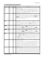
S I G N A L
PIN No.
Type
Description
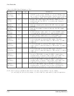
C n E M S G
163
I
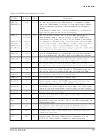
Not engine message. This input signal is used by the printer engine to
send a 1-byte status message in response to a command from the
KS32C6100. When CnEBSY is active, the STA TUS data is sent,
synchronized with COMCLK.
VCLK[1:0]
164, 165
I
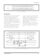
Video shift clock. The VCLK input is a free-running signal that is used to
drive transfers of video data. The two VCLK signals can supplied by the
laser printer engine or by an on-board oscillator.
n E N G P R Q
166
I
Not page synchronize signal request.
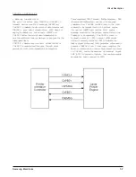
The nENGPRQ input informs the KS32C6100 that the LBP engine is
ready to receive the nCPUPSYNC signal. When the printer engine
receives the nCPUPRINT command from the KS32C6100, it enables
nENGPRQ within a preset time interval. nENGPRQ is disabled
whenever the nCPUPSYNC level goes active Low.
n E N G H S Y N C
169
I
Not engine horizontal synchronize. The nENGHSYNC input is used to
synchronize signals with the horizontal scanning line of a printer engine.
A new line starts with each nENGHSYNC pulse. When nENGHSYNC
goes active, the KS32C6100 sends one row of data to the engine, thereby
maintaining synchronization with video out (VIDEO_OUT).
nCPUPSYNC
170
O
Not page synchronize. The nCPUPSYNC output is used to synchronize
signals with the print of one page. The printer engine waits until
nCPUPSYNC goes active. After a predetermined time interval has
elapsed, the KS32C6100 must send image data synchronized with
nENGHSYNC.
n E N G R E A D Y
171
I
Not engine print ready. This nENGREADY input signal indicates that
the printer engine is ready to print. nENGREADY goes active when
certain status conditions in the printer engine are met.
nCPUPRINT
172
O
Not start print. The nCPUPRINT output is a print command issued by
the KS32C6100. When nCPUPRINT goes active, the printer engine starts
printing. the KS32C6100 must then hold nCPUPRINT to its active state
until nCPUPSYNC becomes inactive.
VIDEO_OUT
173
O
Video data output. The VIDEO-OUT signal carries the actual image data
to be printed by the laser printer. VIDEO-OUT must be synchronized
with nCPUPSYNC for vertical scanning and with nENGHSYNC for
horizontal scanning.
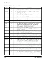
GPIO[15:0]
175~182 I/O
Programmable I/O ports. Each of the sixteen I/O ports can be
185~192
mapped to a specific signal name (to external interrupts, for example).
The port assignments that follow are used as one example of such an
I/O port map.
GPIO[15]:
192
O
Timer 0 output. When a timer 0 time-out occurs, the TIMEOUT0 pulse
TIMEOUT0
is output in predefined time intervals.
GPIO[13]: 190
I
External timer clock input.
TECLK
GPIO[12]: 189
I
Engine power ready. nENGPWR is a status signal from the printer
n E N G P W R
engine. Actually, any I/O port pin can be mapped to input nENGPWR
without any modifications.
Table 1-1 KS32C6100 Signal Descriptions (Cont.)
Samsung Electronics
5-13
Circuit Description
Содержание MSYS 5150
Страница 9: ...2 6 Samsung Electronics Specification Memo ...
Страница 16: ...3 26 Samsung Electronics Setup and Installing Memo ...
Страница 37: ...4 2 Samsung Electronics Theory of Operation ...
Страница 41: ...4 6 Samsung Electronics Memo Theory of Operation ...
Страница 116: ...Samsung Electronics 7 9 Maintenance Troubleshooting No Image ...
Страница 117: ...Samsung Electronics Maintenance Troubleshooting 7 10 ...
Страница 118: ...Samsung Electronics 7 11 Maintenance Troubleshooting All Black ...
Страница 119: ...7 12 Samsung Electronics Maintenance Troubleshooting Vertical White Line Band ...
Страница 120: ...Samsung Electronics 7 13 Maintenance Troubleshooting Dark Image ...
Страница 121: ...7 14 Samsung Electronics Maintenance Troubleshooting Background ...
Страница 122: ...Samsung Electronics 7 15 Maintenance Troubleshooting Ghost ...
Страница 123: ...7 16 Samsung Electronics Maintenance Troubleshooting Black Dot ...
Страница 124: ...Samsung Electronics 7 17 Maintenance Troubleshooting Horizontal Band ...
Страница 125: ...7 18 Samsung Electronics Maintenance Troubleshooting Irregular Density ...
Страница 126: ...Samsung Electronics 7 19 Maintenance Troubleshooting White Spot ...
Страница 127: ...7 20 Samsung Electronics Maintenance Troubleshooting Trembling at the End When OHP Printing ...
Страница 128: ...Samsung Electronics 7 21 Maintenance Troubleshooting Poor Fusing Grade ...
Страница 132: ...Samsung Electronics 7 25 Maintenance Troubleshooting No Power LCD NO display LED Off ...
Страница 133: ...Fuser Error 7 26 Samsung Electronics Maintenance Troubleshooting ...
Страница 134: ...Samsung Electronics 7 27 Maintenance Troubleshooting Paper Jam Mis feeding ...
Страница 135: ...7 28 Samsung Electronics Maintenance Troubleshooting Paper Jam Jam1 ...
Страница 136: ...Samsung Electronics Maintenance Troubleshooting 7 29 Engine Error ...
Страница 137: ...7 30 Samsung Electronics Maintenance Troubleshooting Memo ...
Страница 187: ...9 28 Samsung Electronics Electrical Parts List ...
Страница 189: ...11 Connection Diagram Samsung Electronics 11 1 ...
Страница 190: ...12 1 Main Circuit Diagram Samsung Electronics 12 1 12 Schematic Diagrams ...
Страница 191: ...Schematic Diagrams 12 2 Samsung Electronics Main Circuit Diagram ...
Страница 192: ...Main Circuit Diagram Samsung Electronics 12 3 Schematic Diagrams ...
Страница 193: ...Schematic Diagrams 12 4 Samsung Electronics Main Circuit Diagram ...
Страница 194: ...Main Circuit Diagram Samsung Electronics 12 5 Schematic Diagrams ...
Страница 195: ...Schematic Diagrams 12 6 Samsung Electronics Main Circuit Diagram ...
Страница 196: ...Main Circuit Diagram Samsung Electronics 12 7 Schematic Diagrams ...
Страница 200: ...12 3 Sensors Circuit Diagram Samsung Electronics 12 11 Schematic Diagrams ...
Страница 201: ...Schematic Diagrams 12 12 Samsung Electronics 12 4 Switch Circuit Diagram ...
Страница 202: ...Samsung Electronics 12 13 Schematic Diagrams 12 5 Joint Circuit Diagram ...
Страница 203: ...Schematic Diagrams 12 14 Samsung Electronics 12 6 OPE Circuit Diagram IF Active HIGH Logic IF Active LOW Logic ...
Страница 204: ...Samsung Electronics 12 15 Schematic Diagrams 12 7 PTL Circuit Diagram ...
Страница 205: ...Schematic Diagrams 12 16 Samsung Electronics 12 8 SCAN Circuit Diagram ...
Страница 206: ...Samsung Electronics 12 17 Schematic Diagrams 12 9 Engin Circuit Diagram ...
Страница 207: ...Schematic Diagrams 12 18 Samsung Electronics Engin Circuit Diagram ...
Страница 208: ...Samsung Electronics 12 19 Schematic Diagrams 12 10 LIU Circuit Diagram ...
Страница 210: ... Samsung Electronics Co Ltd Mar 1999 Printed in Korea P N JC68 00097A Rev 1 00 ELECTRONICS ...

