S I G N A L
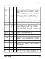
PIN No.
Type
Description
Auxiliary Signals
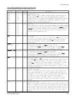
T X ATT[3:1]
38, 39, 40
I
Analog Transmit Attenuation.
The host can cause the modem to attenuate the transmit analog output in
steps of 2dB from 0dB by using the three encoded TXATT[3:1] inputs as
follows:
The TXATT[3:1] lines may be connected directly to 0V or 5V, or to three
GPIO lines used as outputs to select the attenuation under the host
program control.
BYPASS
36
I
Receiver Highpass Filter Bypass Enable.
The state of this pin does not have any effect on the operation of the
modem, but it should tied to 5V or ground.
GP13, GP11
61, 63
I/O
General Purpose I/O
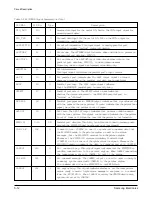
GP[7:2]
5, 4, 3, 2
General Purpose Input/Output
1, 100
GP[21:19]
91, 93, 94
I
General Purpose Input
GP[17:16]
76, 75
N C
19, 20, 27
Unbonded Pins (These are not connected to the internal logic)
28, 29, 31
No Connection
32, 33, 41
51, 62, 73
SYNCIN1
26
I
Eye Sync Input 1, connect to SEPWCLK.
SYNCIN2
74
I
Eye Sync Input 2, connect to SEPWCLK.
Analog Interface
V C
48
O
Center Voltage. 2.5V output and it needs an external capacitor.
RCVI
37
I
Transmitter Disable. When tied to “1”, it disables the transmitter side of
AFE.
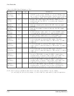
R X A M P I
18
I
Receiver Amplifier Input. This internally tied to pin17 which is Analog
Ground.
SWGAINI
24
I
Externally connected to SWGAINI pin.
V R E F N
42
O
Negative Reference Voltage
A O U T
49
O
Externally connected to bypass capacitor to ground.
Analog Loopback Interface
A D I N
87
I
Analog-to-digital Data In. 1-bit input to the internal decimation filter.
A D O U T
35
O
Analog-to-digital Data Out. 1-bit input to the internal AFE’s RXPA TH.
D A I N
34
I
Digital-to-analog Data In. 1-bit input to the internal AFE’s RXPA TH.
D A O U T
88
O
Digital-to-analog Data Out. 1-bit output from the internal digital
interpolation filter.
Table 2-1 Hardware Interface Signal Descriptions (Cont.)
TXATT3
TXATT2
TXATT1
Attenuation (dB)
0
0
0
0
0
0
1
2
0
1
0
4
0
1
1
6
1
0
0
8
1
0
1
10
1
1
0
12
1
1
1
14
5-22
Samsung Electronics
Circuit Description
Содержание MSYS 5150
Страница 9: ...2 6 Samsung Electronics Specification Memo ...
Страница 16: ...3 26 Samsung Electronics Setup and Installing Memo ...
Страница 37: ...4 2 Samsung Electronics Theory of Operation ...
Страница 41: ...4 6 Samsung Electronics Memo Theory of Operation ...
Страница 116: ...Samsung Electronics 7 9 Maintenance Troubleshooting No Image ...
Страница 117: ...Samsung Electronics Maintenance Troubleshooting 7 10 ...
Страница 118: ...Samsung Electronics 7 11 Maintenance Troubleshooting All Black ...
Страница 119: ...7 12 Samsung Electronics Maintenance Troubleshooting Vertical White Line Band ...
Страница 120: ...Samsung Electronics 7 13 Maintenance Troubleshooting Dark Image ...
Страница 121: ...7 14 Samsung Electronics Maintenance Troubleshooting Background ...
Страница 122: ...Samsung Electronics 7 15 Maintenance Troubleshooting Ghost ...
Страница 123: ...7 16 Samsung Electronics Maintenance Troubleshooting Black Dot ...
Страница 124: ...Samsung Electronics 7 17 Maintenance Troubleshooting Horizontal Band ...
Страница 125: ...7 18 Samsung Electronics Maintenance Troubleshooting Irregular Density ...
Страница 126: ...Samsung Electronics 7 19 Maintenance Troubleshooting White Spot ...
Страница 127: ...7 20 Samsung Electronics Maintenance Troubleshooting Trembling at the End When OHP Printing ...
Страница 128: ...Samsung Electronics 7 21 Maintenance Troubleshooting Poor Fusing Grade ...
Страница 132: ...Samsung Electronics 7 25 Maintenance Troubleshooting No Power LCD NO display LED Off ...
Страница 133: ...Fuser Error 7 26 Samsung Electronics Maintenance Troubleshooting ...
Страница 134: ...Samsung Electronics 7 27 Maintenance Troubleshooting Paper Jam Mis feeding ...
Страница 135: ...7 28 Samsung Electronics Maintenance Troubleshooting Paper Jam Jam1 ...
Страница 136: ...Samsung Electronics Maintenance Troubleshooting 7 29 Engine Error ...
Страница 137: ...7 30 Samsung Electronics Maintenance Troubleshooting Memo ...
Страница 187: ...9 28 Samsung Electronics Electrical Parts List ...
Страница 189: ...11 Connection Diagram Samsung Electronics 11 1 ...
Страница 190: ...12 1 Main Circuit Diagram Samsung Electronics 12 1 12 Schematic Diagrams ...
Страница 191: ...Schematic Diagrams 12 2 Samsung Electronics Main Circuit Diagram ...
Страница 192: ...Main Circuit Diagram Samsung Electronics 12 3 Schematic Diagrams ...
Страница 193: ...Schematic Diagrams 12 4 Samsung Electronics Main Circuit Diagram ...
Страница 194: ...Main Circuit Diagram Samsung Electronics 12 5 Schematic Diagrams ...
Страница 195: ...Schematic Diagrams 12 6 Samsung Electronics Main Circuit Diagram ...
Страница 196: ...Main Circuit Diagram Samsung Electronics 12 7 Schematic Diagrams ...
Страница 200: ...12 3 Sensors Circuit Diagram Samsung Electronics 12 11 Schematic Diagrams ...
Страница 201: ...Schematic Diagrams 12 12 Samsung Electronics 12 4 Switch Circuit Diagram ...
Страница 202: ...Samsung Electronics 12 13 Schematic Diagrams 12 5 Joint Circuit Diagram ...
Страница 203: ...Schematic Diagrams 12 14 Samsung Electronics 12 6 OPE Circuit Diagram IF Active HIGH Logic IF Active LOW Logic ...
Страница 204: ...Samsung Electronics 12 15 Schematic Diagrams 12 7 PTL Circuit Diagram ...
Страница 205: ...Schematic Diagrams 12 16 Samsung Electronics 12 8 SCAN Circuit Diagram ...
Страница 206: ...Samsung Electronics 12 17 Schematic Diagrams 12 9 Engin Circuit Diagram ...
Страница 207: ...Schematic Diagrams 12 18 Samsung Electronics Engin Circuit Diagram ...
Страница 208: ...Samsung Electronics 12 19 Schematic Diagrams 12 10 LIU Circuit Diagram ...
Страница 210: ... Samsung Electronics Co Ltd Mar 1999 Printed in Korea P N JC68 00097A Rev 1 00 ELECTRONICS ...


