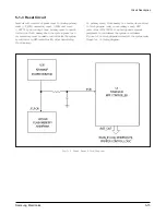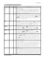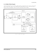
S I G N A L
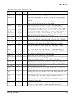
PIN No.
Type
Description
EN85
65
I
Enable 8085 bus mode
When EN85 is connected to ground, 8085 bus mode is selected and the
modem can interface directly to an 8085 compatible microprocessor bus
using READ and WRITE. When EN85 is pulled-up to +5V, 6500 bus
mode is selected and the modem can interface directly to a 6500
compatible micro-processor using
φ
2 and R/W.
X C L K O
70
O
XCLKO output
This output pin is a 12 MHz (KS16116) or 19 MHz (KS16117) square wave
output derived from XTALI.
Y C L K O
71
O
YCLKO output
This output pin is a 6 MHz (KS16116) or 9.5 MHz (KS16117) square wave
output derived from XTALI.
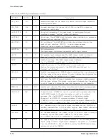
SEPXO
86
O
Serial eye pattern bit data
SEPYO
90
These two outputs provide two serial bit streams containing eye pattern
display data for the oscilloscope X and Y axis. The data words are 9 bits
long with the sigh bit shifted out first and the bits clocked by the rising
edge of SEPCLK.
SEPCLKX
84
O
Serial eye pattern bit clock
SEPCLK is a 230.4 KHz clock used to shift the eye pattern data into the
serial-to-parallel converters. SEPXO and SEPYO are shifted out by the
modem on the rising edge of SEPCLKX.
S E P W C L K
83
O
Serial eye pattern word clock
SEPWCLK (9600Hz) provides SEPXO and SEPYO 9-bit word timing and
its rising edge is used for copying the output of the serial to parallel
converters into the X and Y digital-to-analog converters.
T X A O
44
O
Transmitter analog output
The TXAO can supply a maximum of 2.5 .015 volts into a load
resistance of 10K
Ω
(minimum). An external analog smoothing filter with
transfer function 28735.63/(S+11547.34) is required.
RXAI
45
I
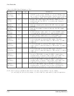
Receiver analog input
The input impedance of RXAI is greater than 1M
Ω
.
An external analog
anti-aliasing filter with transfer function 21551.72/(S+11547.34) is
required between the line interface and the modem RAXI input.
The maximum input signal level into the anti-aliasing filter should not
exceed 0 dBm.
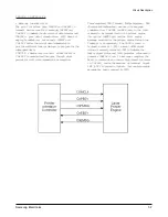
Digital Loopback
SEPCLK
85
O
Over-sampling Clock Output. 2.304MHz clock output. Normally tied to
ECLKIN1.
ECLKIN1
25
I
Over-sampling Clock Input. Input to the AFE’s over-sampling clock
input pin. Normally connected to SEPCLK.
R C V O
98
O
Disable Transmitter Output. “1” on this pin disables AFE’s transmitter.
Normally connected to RCVI.
S W G A I N O
99
O
Externally connected to SWGAINI pin.
Table 2-1 Hardware Interface Signal Descriptions (Cont.)
Samsung Electronics
5-21
Circuit Description
Содержание MSYS 5150
Страница 9: ...2 6 Samsung Electronics Specification Memo ...
Страница 16: ...3 26 Samsung Electronics Setup and Installing Memo ...
Страница 37: ...4 2 Samsung Electronics Theory of Operation ...
Страница 41: ...4 6 Samsung Electronics Memo Theory of Operation ...
Страница 116: ...Samsung Electronics 7 9 Maintenance Troubleshooting No Image ...
Страница 117: ...Samsung Electronics Maintenance Troubleshooting 7 10 ...
Страница 118: ...Samsung Electronics 7 11 Maintenance Troubleshooting All Black ...
Страница 119: ...7 12 Samsung Electronics Maintenance Troubleshooting Vertical White Line Band ...
Страница 120: ...Samsung Electronics 7 13 Maintenance Troubleshooting Dark Image ...
Страница 121: ...7 14 Samsung Electronics Maintenance Troubleshooting Background ...
Страница 122: ...Samsung Electronics 7 15 Maintenance Troubleshooting Ghost ...
Страница 123: ...7 16 Samsung Electronics Maintenance Troubleshooting Black Dot ...
Страница 124: ...Samsung Electronics 7 17 Maintenance Troubleshooting Horizontal Band ...
Страница 125: ...7 18 Samsung Electronics Maintenance Troubleshooting Irregular Density ...
Страница 126: ...Samsung Electronics 7 19 Maintenance Troubleshooting White Spot ...
Страница 127: ...7 20 Samsung Electronics Maintenance Troubleshooting Trembling at the End When OHP Printing ...
Страница 128: ...Samsung Electronics 7 21 Maintenance Troubleshooting Poor Fusing Grade ...
Страница 132: ...Samsung Electronics 7 25 Maintenance Troubleshooting No Power LCD NO display LED Off ...
Страница 133: ...Fuser Error 7 26 Samsung Electronics Maintenance Troubleshooting ...
Страница 134: ...Samsung Electronics 7 27 Maintenance Troubleshooting Paper Jam Mis feeding ...
Страница 135: ...7 28 Samsung Electronics Maintenance Troubleshooting Paper Jam Jam1 ...
Страница 136: ...Samsung Electronics Maintenance Troubleshooting 7 29 Engine Error ...
Страница 137: ...7 30 Samsung Electronics Maintenance Troubleshooting Memo ...
Страница 187: ...9 28 Samsung Electronics Electrical Parts List ...
Страница 189: ...11 Connection Diagram Samsung Electronics 11 1 ...
Страница 190: ...12 1 Main Circuit Diagram Samsung Electronics 12 1 12 Schematic Diagrams ...
Страница 191: ...Schematic Diagrams 12 2 Samsung Electronics Main Circuit Diagram ...
Страница 192: ...Main Circuit Diagram Samsung Electronics 12 3 Schematic Diagrams ...
Страница 193: ...Schematic Diagrams 12 4 Samsung Electronics Main Circuit Diagram ...
Страница 194: ...Main Circuit Diagram Samsung Electronics 12 5 Schematic Diagrams ...
Страница 195: ...Schematic Diagrams 12 6 Samsung Electronics Main Circuit Diagram ...
Страница 196: ...Main Circuit Diagram Samsung Electronics 12 7 Schematic Diagrams ...
Страница 200: ...12 3 Sensors Circuit Diagram Samsung Electronics 12 11 Schematic Diagrams ...
Страница 201: ...Schematic Diagrams 12 12 Samsung Electronics 12 4 Switch Circuit Diagram ...
Страница 202: ...Samsung Electronics 12 13 Schematic Diagrams 12 5 Joint Circuit Diagram ...
Страница 203: ...Schematic Diagrams 12 14 Samsung Electronics 12 6 OPE Circuit Diagram IF Active HIGH Logic IF Active LOW Logic ...
Страница 204: ...Samsung Electronics 12 15 Schematic Diagrams 12 7 PTL Circuit Diagram ...
Страница 205: ...Schematic Diagrams 12 16 Samsung Electronics 12 8 SCAN Circuit Diagram ...
Страница 206: ...Samsung Electronics 12 17 Schematic Diagrams 12 9 Engin Circuit Diagram ...
Страница 207: ...Schematic Diagrams 12 18 Samsung Electronics Engin Circuit Diagram ...
Страница 208: ...Samsung Electronics 12 19 Schematic Diagrams 12 10 LIU Circuit Diagram ...
Страница 210: ... Samsung Electronics Co Ltd Mar 1999 Printed in Korea P N JC68 00097A Rev 1 00 ELECTRONICS ...

