background image

I-

27

BF-Sirius

Operation Manual

3.10 Basic Functional Items

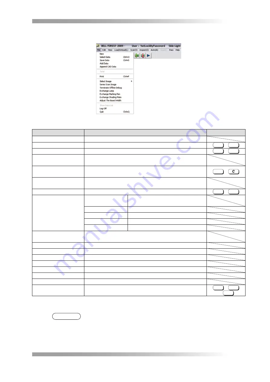
Selectable Items from the File Menu

FFFure 

3-3

Items 

Description

Shortcut Key

New

Makes the inspection data.

Select Data

Selects the inspection data.

Ctrl

 + 

O

Save Data

Saves the inspection data.

Ctrl

 + 

S

Add Data

Combines  other  inspection  data  with  the  currently  selected 
inspection data.

Append CAD Data

Expands the CAD data and makes an inspection window on the 
component's position.

Ctrl

 + 

Total

Makes a data file of the inspection result for NG component with 
the data / time.

Print

Displays the layout when printing.

Ctrl

 + 

P

Select Image 

Transfers  Images  to 
Off-line Teacher

Sends data to BF-Editor. (*1)

Opens Images

Calls up the saved image.

Saves Images

Saves the image in the specified folder.

Saves OK Images

Not available.

Opens OK Images

Not available.

Series Scan Image

Save or delete the image that are used for inspection data 
debugging.

Terminate Offline Debug

Not available.

Exchange Lamp

Not available.

Exchange Marking Pen

Not available.

Exchange Shading Plate

Not available.

Adjust The Board Width

Not available.

Show Data List

Not available.

Log Off

Logs in the inspection software again when using privilege setup.

QuFt

Quit the inspection software.

Ctrl

 + 

Q

or 

F12

Items under the File Menu and their Shortcut Keys

T

a

bl

3-

NOTE

  (*1) BF-Editor is the optional system to make / edit inspection data on separate PC terminal.

Содержание BF-Sirius

Страница 1: ... SJ241DCM1 02E BF Sirius Manual ...

Страница 2: ...al Copyright 2011 Saki Corporation All Rights Reserved Printed in Japan Notations used in this manual Notation Meaning DANGER DANGER indicates an imminently hazardous situation which could be threat to life or cause serious injury WARNING WARNING indicates a potentially hazardous situation which could be threat to life or cause serious injury CAUTION CAUTION indicates a potentially hazardous situa...

Страница 3: ...rticles Using the system in an environment in violation of the operating conditions described in the Manual can cause fire or electric shock To avoid damage to the cable the following actions should never be performed bending the cord by force pulling the cord or placing it near heating equipment To avoid electric shock or fire damaged power supply cords or loose outlets should not be used To avoi...

Страница 4: ...reaker To avoid burns or injury let the electric components and units cool down sufficiently Do not put a hand or any object in the driven section during the machine running It may result in personal injury To avoid malfunction or accidents do not touch any system internal structure with the exception of components described in this manual Connect the ground lead to prevent electric shock in the e...

Страница 5: ... Check 3 2 1 I 9 Turn on the Machine 3 2 2 I 9 Turn on the PC and Start the Inspection Software 3 2 3 I 10 Check before Start Inspection 3 2 4 I 11 System Shutdown 3 3 I 12 Quit the Inspection Software 3 3 1 I 12 Check at Closing of Work 3 3 2 I 14 Long Term System Shutdown 3 3 3 I 14 Select Inspection Data 3 4 I 15 Loading Unloading a PCB 3 5 I 17 Guide Width Adjustment Method 3 5 1 I 17 PCB Load...

Страница 6: ...ing Optical System 1 3 II 3 Preparations for Optical Parts Cleaning 1 3 1 II 4 Cleaning Shading Sheet 1 3 2 II 5 Cleaning Diffuser 1 3 3 II 5 Cleaning Light Control Film 1 3 4 II 7 Cleaning Telecentric Lens Mirror and Camera Lens 1 3 5 II 8 Greasing up 1 4 II 11 Adjustment Replacement and setting of Main Parts 2 II 13 Sensor Adjustment 2 1 II 13 Type A Dog Sensor 2 1 1 II 13 Type B Reflective Boar...

Страница 7: ...I 1 BF Sirius Operation Manual Operation Manual ...

Страница 8: ...ead illumination Side Light and LowLight enable acquiring three kinds of the images only in one pass By using line sensor camera the system achieve high definition images of 18 μm Shading technology compensates image brightness automatically so that it will always be under the same conditions The telecentric lens optics increases inspection accuracy By this accuracy improvement virtually distortio...

Страница 9: ...t EC05 Power Outlet for PC A outlet to supply power for PC EC06 Power Outlet for LCD Monitor A outlet to supply power for LCD monitor LU01 Power Lamp Turn on the machine and the lamp lights on SW01 Main Breaker Breaker which regulates the power supply POWER stand for main breaker SW02 Start Switch Used in Auto Mode Push this switch after unloading loading PCB and start scanning and inspection STAR...

Страница 10: ...l machine CP01 CP02 CP03 FN01 FN02 MC06 02 MC06 01 FN05 FN04 FN03 MC01 MC02 MC03 MC04 02 MC05 MC04 01 MR01 NF01 PB19 01 PB19 02 PB20 PB21 01 PB21 02 EC07 MD01 PB17 PB24 PB23 PS03 PS02 PS04 PS01 TB01 Internal Left Side View Internal Top Layer View Internal Rear View Bottom Layer View Internal Right Side View Internal View FFFFFFFFFFF ...

Страница 11: ...otor SJMR2R011 MR01 Scan Motor During scanning this motor moves the scan table SJ24EH041 NF01 Noise Filter Filters out noise from the input AC power supply SJEC1N012 PB17 Option Signal Board Relays the signals to the PLC SJPB2GA00 PB19 01 Image Processing Board 1 Performs signal conversions so that images scanned by the right side CCD Unit can be transferred to the PC SJPB1GA00 PB19 02 Image Proce...

Страница 12: ...4 SR03 Board Sensor A sensor that detects whether a PCB is set in the correct position SJ24EH025 SR04 Scan Start Sensor When this sensor is sensed start scaning SJ03PE014 SR05 Rear Scan Limit Sensor When this sensor is sensed the scan motor stops beyond which the scan table cannot move any further rearward SJ03PE014 SS01 01 02 Area Sensor Senses whether a hand or an object is caught in the inlet a...

Страница 13: ...nes sound and the motor stops immediately The system operation is suspended NOTE The motor turns off and the scan table can be moved manually So you can respond to the case that any object inside the machine is detected during the operation or there is any object which is inserted in the scan table E MERGE N C Y Reset Switch Emergency Stop Switch Push Release Top View Reset Switch and Emergency St...

Страница 14: ...nd resume usual image scan operation Step5 3 1 2 Area Sensor Area sensor watches safe operation of shading procedure and image scanning When area sensor is sensed beep tones sound and the motor stops immediately The system operation is suspended Upper Area Sensor Front Area Sensor Area Sensor FFFFFFFFFFF When area sensor senses and stops the dialog shown in Figure 3 4 appears Remove any object sen...

Страница 15: ...onnection cables All power supply cords and connection cables are connected firmly and correctly There is no object on the scan table There is no object which hinders table motion There is no object on the machine There is no foreign object inserted in the entrance of the machine 3 2 2 Turn on the Machine Turn on the earth leakage breaker on the rear side of the machine and turn the main breaker S...

Страница 16: ...Login Window FFFFFFFFFFF When the login process is successful the inspection software BF1 exe for the system is Step2 automatically activated NOTE If it fails to start automatically double click BF Sirius shortcut icon on the desktop to start the inspection software FFFFFFFFFFF BF Sirius Shortcut Icon The dialog shown in Figure 3 8 appears Step3 If the power of the machine is already on press OK I...

Страница 17: ...FFFFFFF 3 2 4 Check before Start Inspection Before starting inspection check the followings If any problem occurs please contact Saki Corporation or our representatives The power lamps of the machine and the PC lights on There is neither smoke nor a unusual smell There is no abnormal noise at the time of system activation The inspection software starts normally ...

Страница 18: ...Figure 3 11 appears Step2 OK Press if you backup the data in E drive Cancel Press if you do not prefer to backup the data in E drive Backup Confirmation FFFFFFFFFFFF The dialog shown in Figure 3 12 appears Step3 For default setting save the inspection data into D BF1 BF1DATA To save another destination check Change destination to save inspection data and specify the directory to save NOTE Recommen...

Страница 19: ... Data Files Confirmation FFFFFFFFFFFF ii Save the inspection data file of the same PCB name or the group name by overwriting the exist data OK Saves the data by overwriting basis and go to Step4 Cancel Returns to the original inspection window without saving the data Overwrite Saving Confirmation FFFFFFFFFFFF After confirmed saving inspection data the dialog shown in Figure 3 15 appears Step4 OK Q...

Страница 20: ...e PC wait for about one minute before restarting the PC 3 3 2 Check at Closing of Work After system shutdown check the following items for the next inspection When any problem occurs please contact Saki Corporation or our representatives The power lamps of the machine and the PC lights off There is neither smoke nor a unusual smell There is no damage on the inspection machine There is no damage in...

Страница 21: ...ta in E drive Cancel Press if you do not prefer to backup the data in E drive Backup Confirmation FFFFFFFFFFFF The dialog shown in Figure 3 20 appears Step3 For default setting save the inspection data into D BF1 BF1DATA To save another destination check Change destination to save inspection data and specify the directory to save NOTE Recommend to save the inspection data either make the new data ...

Страница 22: ...e data Make New Data Files Confirmation FFFFFFFFFFFF ii Save the inspection data file of the same PCB name or the group name by overwriting the exist data OK Saves the data by overwriting basis and go to Step4 Cancel Returns to the original inspection window without saving the data Overwrite Saving Confirmation FFFFFFFFFFFF The dialog shown in Figure 3 23 appears Select inspection data and press S...

Страница 23: ...t front side of the guide rail Step2 Adjust the rail width and fix the clamp lever Step3 CAUTION When you inspect large PCB support PCB using sub backup pin Sub backup pin set position without components 3 5 2 PCB Loading Unloading Method Put the PCB close against front side of the guide rail and carefully put the other side of the PCB on the back side of the guide rail Position the PCB leaning th...

Страница 24: ...Coordinate Index Display Inspection Result Operation Mode Explanation of Index Frame FFFFFFFFFFFF NOTE Index Display can be selected from the following formats Select View Results from the menu bar Display the corresponding components in Component Data Worst 20 Rank the components in which defects are found by the number of occurrences and display the worst 20 components False 20 Rank the componen...

Страница 25: ...rvention in manual operations such as loading or unloading PCBs MANUAL MODE System Start Scan Inspect Select Data Edit Data Advanced System Setting Save Data Select Data Scan Inspect Advanced System Setting Save Data AUTO MODE Edit Data Command Scan Inspect Command System End Auto Stop System End Load PCB Start Switch Unload PCB Edit Data NG Judge Manual Operation Diagram of the System Basic Behav...

Страница 26: ...the PCB manually Operation Procedure in Manual Mode TTTTTTTTTT 3 8 2 Inspection Method of Manual Mode Select a data according to Step1 3 4 Select Inspection Data Put a PCB to inspect on the scan table Step2 Press Step3 Scan button on the tool bar or select Scan from the menu bar After the PCB image is displayed on the window check the image display for distortion or Step4 tilt If the image is dist...

Страница 27: ...n Auto running 4 Result output 5 Unloading the PCB Unload the PCB manually 6 Check the OK NG judgement Judge the result by OK or NG Repeat from Step 1 to Step 6 Operation Procedure in Auto Mode TTTTTTTTTT 3 9 2 Inspection Method of Auto Mode Press Step1 Auto button on the tool bar or select Auto from the menu bar The dialog shown in Figure 3 30 appears Auto Mode Setup FFFFFFFFFFFF Set necessary se...

Страница 28: ... Figure 3 31 appears Press Step4 OK Starting Auto Inspection FFFFFFFFFFFF The dialog shown in Figure 3 32 appears Step5 If OK is pressed the scan table returns to the origin position and Waiting for Start dialog appears Return to the Origin FFFFFFFFFFFF ...

Страница 29: ...ents Not available Monitor Mode Not available Make NG files Save the as many NG data as the preset number of PCBs in the same file If you enter the number of NG data and check this item the making interval of the NG file can be set e g If enter 25 it can save NG data equivalent to the number of magazine rack in one file Lot Number Set the lot number of the PCB The inspection result is stored in th...

Страница 30: ...e is scanned and inspected automatically If any components are detected the dialog shown in Figure 3 35 appears Input Repair Person s Name FFFFFFFFFFFF In Step2 Input Repair Person s Name dialog either type in the name of the operator or select one from the list OK Goes to the Step3 Delete Deletes the selected name from the list NOTE Input Repair Person s Name dialog will not be re displayed if it...

Страница 31: ...m is described in Table 3 4 and 3 5 NOTE It enables to start scanning next PCB while judging the result B A C D Edit NG Component Data FFFFFFFFFFFF A Upper Right Image Show the point that the result will be NG B Upper Left Image Show the position of upper right image using yellow lines By comparing these two images A and B with the actual PCB determine a good PCB vs a defective PCB and whether the...

Страница 32: ... Auto Mode Setup Item Description Macro Code Indicates the component name NG Type K L Indicates the defect type K of the component shown in the upper right image and the test result L Idle Count Indicates the number of NG PCBs waiting for judgement which were scanned while judging certain PCB REPAIR Press if the inspection result is NG and the PCB is indeed defective OK Press if the inspection res...

Страница 33: ...Image Transfers Images to Off line Teacher Sends data to BF Editor 1 Opens Images Calls up the saved image Saves Images Saves the image in the specified folder Saves OK Images Not available Opens OK Images Not available Series Scan Image Save or delete the image that are used for inspection data debugging Terminate Offline Debug Not available Exchange Lamp Not available Exchange Marking Pen Not av...

Страница 34: ...ark Changes the sub mark data Adjust Mark1 Mark2 Makes the fiducial mark compensation Edit Library Copies the inspection library between groups Link Library Assigns the library window to each component and display a window layout on the PCB Unlink Library Unlink library and go back to CAD data spread status Library Tree A management window with images for marking library classification and selecti...

Страница 35: ... reference name Rename Component Right click and edit the component s reference name Side A Displays the side A of the PCB image Side B Not available Results Worst 20 Displays the worst 20 components data False 20 Display the worst 20 of false components data NG Displays the defective components OK Displays the OK components Clear NG Data Clears the NG components XY Offset Chart Displays the compo...

Страница 36: ...s Scan Starts scanning S Inspect Inspects the scanned image and displays the inspection result I Auto Starts the automatic running A Stop Stops the runnning E Help Version Shows the version information of the software Help Calls up HELP Other Items and Their Shortcut Keys TTTTTTTTTT ...

Страница 37: ...II 1 BF Sirius Maintenance Manual Maintenance Manual ...

Страница 38: ...ure may cause the machine malfunction or unanticipated accident Quit the inspection software and the OS Step1 Turn off the main breaker Step2 Turn off the earth leakage breaker Step3 Unplug the power supply cord Step4 1 2 How to Remove External Cover Loosen the four M4 cross recessed head screws anti drop type and remove the top of external Step1 cover CAUTION The removed external covers must be h...

Страница 39: ...heet Wipe off any dirt gently with a dry and soft cloth or paper 1 Every 6 months Light Control Film Wipe off any dirt gently with a dry and soft cloth or paper In case of heavy dirt soak a dry and soft cloth or paper in ethanol or glass cleaner and wipe them out 2 Camera Lens Telecentric Lens Mirror Diffuser Cleaning Method TTTTTTTTTT CAUTION The maintenance interval above is a standard period ho...

Страница 40: ...gloves when cleaning mirrors or handling solvent Lint free Wiper Swab Ethanol or Glass Cleaner Gloves Wear gloves when cleaning mirrors or handling solvent Necessary Tools FFFFFFFFFFF Points of Cleaning 1 Wipe off in a constant direction to prevent scratching for mirror or lens 2 Wipe off with dry wiper or swab not to leave the solvent Points of Cleaning FFFFFFFFFFF ...

Страница 41: ... chemicals Wipe off the shading sheet not to bend it CAUTION Change the shading sheet if it is excessively dirty or discolored Shading Sheet Cleaning Shading Sheet FFFFFFFFFFF 1 3 3 Cleaning Diffuser Remove the top of external cover Step1 Disconnect the two connectors of LED lighting unit Step2 Connector Disconnect Connector FFFFFFFFFFF ...

Страница 42: ...the two M4 cap screws and detach the LED lighting unit as shown in Figure 1 8 Step4 WARNING Detaching the LED lighting unit could cause trouble such as image distortion If a regular maintenance is required please contact Saki Corporation CAUTION When removing the LED lighting unit hold both edges of the lighting unit not to touch the LEDs 3 2 1 M4 Cap Screw Remove LED Lighting Unit FFFFFFFFFFF ...

Страница 43: ...Diffuser FFFFFFFFFFF 1 3 4 Cleaning Light Control Film WARNING Regarding the cleaning optical system if the cleaning procedure is not operated in an appropriate way it could cause troubles such as image misalignment If a regular maintenance is required please contact Saki Corporation Remove the two M3 cap screws and detach the light control film case Step1 M3 Cap Screw Light Control Film Case Remo...

Страница 44: ...nce is required please contact Saki Corporation Remove the four M3 cap screws to remove the mirror cover Use dry wiper to wipe gently Step1 both sides of half mirror If it is excessively dirty soak a lint free wiper in ethanol and wipe the half mirror to the longitudinal direction WARNING It is possible to detach the half mirror by removing the screws which secure the mirror clamper Regarding the ...

Страница 45: ...tric lens along the Step2 chase Telecentric Lens Cleaning Telecentric Lens FFFFFFFFFFFF Remove the two M4 cap screws to lift up the cover as shown in Figure 1 14 Step3 Remove the four M4 cap screws to remove the lens cover Step4 M4 Cap Screw M4 Cap Screw Cover Lens Cover Remove Lens Cover FFFFFFFFFFFF ...

Страница 46: ...per is recommended reducing solvent leftover Evaporated Surface Evaporated Surface Evaporated Surface Half Mirror Total Reflection Mirror Cleaning Mirror FFFFFFFFFFFF Soak a lint free wiper in ethanol or glass cleaner and wipe camera lens Step6 CAUTION Wiping camera lens with dry wiper is recommended reducing solvent leftover Camera Lens Cleaning Camera Lens FFFFFFFFFFFF After cleaning is complete...

Страница 47: ...ange depending on the usage environment of the machine Supplier Model Flammable Attribution Exchange Volume Shin Etsu Chemical Co Ltd G 30M Extremely Low Risk 20 cc Applied Grease TTTTTTTTTT CAUTION If the grease attached on your hand or body wipe off with dry cloth or waste cloth Afterwards rinse with soup and flowing water In case of grease is dropped on the floor wipe it with a waste cloth then...

Страница 48: ... greasing is completed attach spring washer and spring guide at initial position M3 cross recessed head screw Grease up Points Greasing up 3 FFFFFFFFFFFF Spring Spring Guide Washer Greasing up 4 FFFFFFFFFFFF Likewise grease up eight points described shown in Figure 1 19 Step4 Reassemble the parts in an opposite procedure Step5 ...

Страница 49: ...stment No Name Sensor Type SR01 Scan Origin Sensor Type A SR02 Front Scan Limit Sensor SR03 Board Sensor Type B SR04 Scan Start Sensor Type A SR05 Rear Scan Limit Sensor SA01 Fiberoptic Sensor Amplifier Type C Sensor Type TTTTTTTTTT 2 1 1 Type A Dog Sensor Dog sensor does not need to adjustment It adjusted appropriate position at the shipment Detect Sensor Type ON OFF Type A Adjust Origin or Limit...

Страница 50: ... Intensity Power Mode Switch Set to the SEL Manual Button Up Down MODE SET Function Setting D L L on Power Mode FINE Sensitivity Setting Method Std Detection Mode Std Timer Function OFF APC Function OFF Eco Function OFF Fiberoptic Sensor Amplifier FFFFFFFFFFF Fiberoptic Sensor Amplifier TTTTTTTTTT Settings 2 2 Maintenance Parts Table 2 4 shows parts that need to be replaced and approximate time fo...

Страница 51: ...t If you wish to request maintenance please contact Saki Corporation 1 TOP LED Lighting FFFFFFFFFFF 2 3 4 4 3 2 4 4 3 5 5 SIDE LOW LED Lighting Assembly FFFFFFFFFFF No Item Qty Replacement Assembly 1 TOP LED Board A SJPB2PC00 1 2 SIDE LED Board B SJPB2NA00 4 SIDE LOW LED Lighting Assembly Including Metal Frame SJ24OPG00 3 SIDE LED Board C SJPB2NK00 4 4 LOW LED Board D SJPB2NL00 12 5 Diffuser SJ24O...

Страница 52: ... 2 3 1 Image Processing Board Switches on the image processing board has each own settings SW0 SW1 SW2 SW3 SW4 SW5 SW6 SW7 ON OFF Image Processing Board FFFFFFFFFFF Item SW0 SW1 SW2 SW3 SW4 SW5 SW6 SW7 Dip Switch Setting OFF OFF OFF OFF OFF OFF OFF OFF Dip Switch Setting TTTTTTTTTT 2 3 2 Option Signal Board Switches on the option signal board has each own settings PASS PASS Normal Normal SW1 SW2 O...

Страница 53: ...t change the value of Current Adjusting Volume on scan motor driver SW0 SW1 SW2 SW3 ON OFF DATA1 DATA2 Current Adjusting Volume Scan Motor Driver FFFFFFFFFFF Item DATA1 DATA2 Motor Step Angle Setting 6 6 Motor Step Angle Setting TTTTTTTTTT Item SW0 SW1 SW2 SW3 Dip Switch Setting ON ON ON ON Dip Switch Setting TTTTTTTTTT ...

Страница 54: ...06 SJ24EH006 SJ24EH007 SJ24EH007 SJ24EH009 SJ24EH010 SJ24EH011 SJ24EH012 SJ24EH013 SJ24EH013 SJ24EH014 SJ24EH014 SJ24EH009 SJ24EH009 SJ24EH010 SJ24EH010 SJ24EH011 SJ24EH011 SJ24EH012 SJ24EH012 SJ00PE005 SJ00PE005 SJ24EH043 SJ24EH044 SJ24EH045 SJ24EH046 SJ24EH045 ACLC M26 MOLD 00 23 ACLC M26 MOLD 00 23 SJ24EH062 CN402 CN404 CN403 CN401 CN407 CN410 CN409 CN502 CN503 CN410 CN409 CN408 CN401 CN402 DSU...

Страница 55: ...CNSMD3 CNSMD1 CNSMD2 CNCF1 CNCF1 CNCF2 CNCF2 CNCF3 CNCF3 CNCF3 CNCF3 CNCF3 CNCF3 CNBS CNBS CNSW1 CNSW1 CNDCPL1 CNDCPL1 CN226 CNX0 7 CNY0 7 CNX8 F CNY8 F SJ24EH030 SJ24EH031 SJ24EH032 SJ24EH033 SJ24EH034 SJ24EH035 SJ24EH036 SJ24EH037 SJ24EH038 SJ24EH039 SJ24EH901 CN302 CN308 CN309 CN301 CN306 SJ24EH040 SJ24EH042 SJ24EH041 SJ24EH044 SJ24EH045 SJ24EH047 SJ24EH048 SJ24EH049 SJ24EH904 SJ24EH905 SJ24EH9...

Страница 56: ... Maintenance Manual 2 5 Safety Circuit Diagram 1 2 3 1 2 24V To Stepping Motor Driver RL1 RL3 RL4 EMG Reset GND JP3 GND RL2 Area Sensor Origin Sensor Limit Sensor CN19 4 5 CN21 1 2 Safety Circuit Diagram FFFFFFFFFFFF ...

Страница 57: ...ing 3 2 Backing up in C Drive This section describes how to save the inspection software its settings and inspection data in C drive Open the folder named Step1 C BF1 Backup Create a new folder by assigning the date as a name Step2 e g January 23 2011 Folder name 20110123 Copy and save all files in Step3 C BF1 to the newly created folder 3 3 External Backup This section describes how to save a bac...

Страница 58: ...hing appears on the monitor The power for the monitor may be off Push the power supply switch on the front side of the monitor The power supply cord on the back of the monitor may be unplugged Securely plug the power supply cord The signal line on the back of the monitor may be unplugged Securely plug the signal line The signal line to the PC monitor may be unplugged The VGA card for the PC may be...

Страница 59: ...he shading sheet the half mirror the lenses and the diffusers Horizontal lines can be seen in scanned image Reinsert the signal line connector from the CCD unit to the PC Image sways Please contact Saki Corporation Noisy image Reinsert the signal line connector from the CCD unit to the PC Rewire the machine by isolating the LAN cables in the machine from the signal lines leading from the CCD unit ...

Страница 60: ...ror Warning Message Description and Recovery Method Release the Emergency switch and push the Reset switch A reset confirmation dialog from the emergency stop condition Push the reset switch after releasing the emergency stop condition The servo motor is off Do you want to continue GetImageStatus is failed EMERGENCY button is pushed Luminance adjustment was failed The software can not complete the...

Страница 61: ...BF Sirius Installation Manual III 1 Installation Manual ...

Страница 62: ...tallation Process TTTTTTTTTT 1 2 Unpacking and Installing the Machine 1 2 1 Items to be Verified at Unpacking Before starting installation check the items If any damaged or missing items are found please contact Saki Corporation No Item Qty 1 Inpsection Machine 1 2 19 inch LCD Monitor 1 3 PC 1 4 Keyboard 1 5 Mouse 1 6 Mouse Pad 1 7 Power Supply Cord 1 8 Power Supply Cord for the System 2 9 Manual ...

Страница 63: ...hine should be installed on a flat vibration free table 4 mm 1272 mm 26 mm 4 mm 26 mm 792 mm 277 mm PCB Front View Side View Installation Condition FFFFFFFFFFF 1 2 3 Remove the Fixing Plate Remove the four M4 cap screws to remove the fixing plate M4 Cap Screw Fixing Plate Remove the Fixing Plate FFFFFFFFFFF ...

Страница 64: ...nect the power supply cord to the main machine Insert connectors and consents firmly and fix them CAUTION When the main machine is move to other place make sure to heft both side of the main machine 1 2 Mouse Keyboard Network Optional Printer CL3 CL4 CL1 CL2 Power Supply Cord Power Supply Cord LAN Cable Printer Cable RS 232C Cable Camera Link Cable CL4 CL2 DVI Terminal LCD Monitor Rear View PC Rea...

Страница 65: ...BF Sirius Specification Customer Support IV 1 Specification Customer Support ...

Страница 66: ... Environment Signal phase 100 to 120V 200 to 240V 10 50 60Hz 700VA Noise Level 60 5 dB Target Board PCB Size 50 W x 50 L to 460 W x 500 L mm 1 97 W x 1 97 L to x 18 11 W x 19 69 L in PCB Thickness 0 6 to 2 5 mm 0 02 to 0 098 in PCB Weight 6 kg 13 2 lb or less Material Glass Epoxy Paper Phenol Ceremic Warpage 2 mm 0 08 in or less PCB Clearance Top 40 mm 1 57 in 1 PCB Clearance Bottom 60 mm 2 36 in ...

Страница 67: ...oximately 18 sec for 460 W x 500 L mm 18 11 W x 19 69 L in size PCB Image Scanning Time Approximately 10 sec 3 Calculating Time Approximately 3 sec 10 000 inspection windows 4 Pre Scan Function 2nd PCB can be processed while reviewing 1st PCB inspection result Inspection Result Output Screen display of defect locations File output of defect details Image output of defective area Network output of ...

Страница 68: ...service representatives carry out installation at delivery Transportation of the product or changing the site of the product after the delivery will be charged Be sure to contact us in order to avoid troubles caused by the transportation Repairs Saki Corporation can provide repair services at customer site Our representatives or Saki Corporation s service representatives will visit customer s fact...

Страница 69: ...rther inquiries please contact Saki Corporation 2 1 4 Others Property Rights of the Replacement Parts The old parts replaced by the repair and necessary for the investigation become our property so please be forewarned Holding Period of the Maintenance Parts Basically replacement parts required to maintain product function will be kept in stock for at least 5 years after termination of production ...

Страница 70: ...d and flood damages gas damages salt damages and the like or by external factors such as connected equipment abnormalities and computer viruses 2 Failure and damage caused by inadequate repair conversion connection and the like made by Customer or intentional breakage 3 Failure and damage caused by inadequate use by Customer such as transportation moving and dropping after delivery 4 Loss after de...

Страница 71: ...d terminate the service to be rendered of Software without making any advance notice to or without obtaining agreement with Customer Saki shall not bear any responsibility for any damages caused by the alteration delay stop and termination of the service to be rendered of Software Article 8 Software Saki may modify specifications or contents and alter distribution method of Software without making...

Страница 72: ...ing Germany DIRECTIVE 2006 42 EC Machinery Directive 2006 95 EC Low Voltage Directive 2004 108 EC EMC Directive The above product has been evaluated for conformity with above directives using the following European standards The technical construction file TCF for this product is retained at the above manufacturer s location Machinery Directive Low Voltage Directive EN ISO12100 1 2003 A1 2009 EN I...

Отзывы: