


Ext. switch 1
Int. switch 1
CPU 1
Int. switch 2
CPU 2
CFIP1
CFIP2
User
dat
a
MM
dat
a
Port 1
Port 2
Port 3
Mng
WAN
WAN
Mng
Ext. switch 2
User
dat
a
MM
dat
a
Port 1
Port 2
Port 3
VLAN B
VLAN A&B
VLAN B
VLAN B
VLAN B
VLAN A
VLAN A
VLAN A&B
VLAN A
User
data
User
data
VLAN A
LAN1
LAN1
LAN2
LAN2
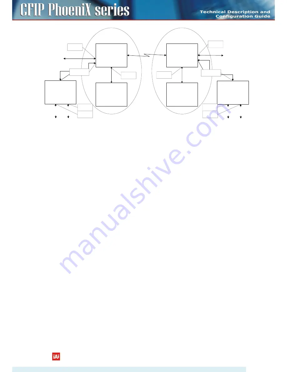
Figure 4.47
Configuration with management and user VLANs on separate LAN ports
For both switches:
VLAN A is configured as:
-
Trunk type VLAN with LAN1 & WAN membership;
-
Access type VLAN with LAN2 & WAN membership with removing and inserting VLAN
tags while packet is being transmitted to LAN2 and WAN, respectively.
VLAN B is configured as:
-
Management type VLAN with LAN1, WAN and Mng ports membership when removing
VLAN tags while packet is being sent to Mng port and inserting tag while packet is
transmitting to LAN&WAN ports.
Limitations and rules on using VLAN:
•
Supports up to 4096 full range VLAN IDs.
•
Only one VLAN with unique IDs is allowed. When adding a different VLAN with the same IDs,
the old VLAN is deleted (also the other types of VLANs).
•
Simultaneous use of Access and Trunk type VLANs on one LAN port is not allowed.
•
After the VLAN table initialization is completed, 802.1Q VLAN mode must be enabled.
•
WAN (P5) allows using only Trunk VLAN Type and Management (P6) – only Access VLAN Type
•
In order to pass untagged packets through the link, VLAN ID “0” should be added as Trunk
VLAN Type on LAN (P1-4) and WAN (P5).
Steps required for VLAN configuration:
1) Add preferable VLAN IDs in “Configuration
VLAN Configuration” in Web GUI on both sides of the
link;
2) Enable “802.1Q VLAN” for remote unit first, then for the local unit;
3) Configure switches for VLAN tag encapsulation on both ends of the link;
4) Reconnect to Web GUI via configured Management VLAN ID.
Examples of VLAN usage:
CFIP PhoeniX Series TDM/IP Split Mount System Technical Description and Configuration Guide
•
Rev. 1.13
•
© SAF Tehnika JSC 2015
71


