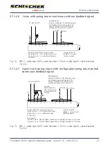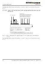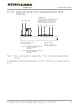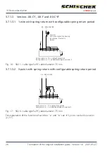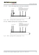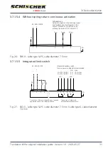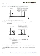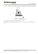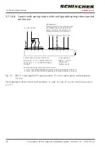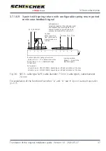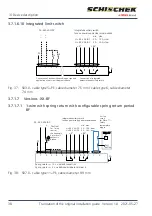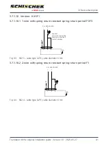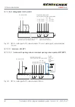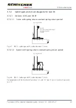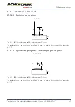
3.7.1.5.4 Without spring return continuous activation
Self-adaptation:
24...240 VAC/DC
~
~
–
+
PE
1
2
PA
3
4
5
YmA
T
GND
UVDC
Automatic alignment of positioning signal
and feedback signal with regard to the
angle of rotation (or travel) is done by
pressing the button (T) for at least 3 s.
Fig.
26: SB6.0 - cable type 5+PE, cable diameter 7.5
mm
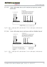
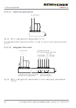
3.7.1.5.5 Integrated limit switch
Integrated auxiliary switch,
fuse on power supply side recommended.
Connection of drive unit depending on type and
application as per circuit diagrams above
Connection of integrated,
potential-free auxiliary switch
24...240 VAC/DC
~
~
–
+
PE
1
2
3
4
PA
a
b
1
2
3
4
5
6
< 5°
> 85°
U < 90 V AC/DC
U > 90 V AC/DC
2 A 10 A, slow
5 A 10 A, slow
min. max.
Fig.
27: SB3.0 - cable type 5+PE, cable diameter 7.5
mm / cable type 6, cable diameter
7.4
mm
3 | Device description
Translation of the original installation guide · Version 1.0 · 2021-05-27
31

