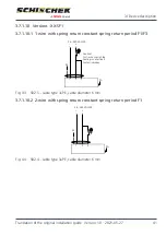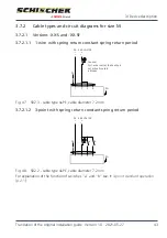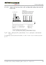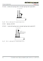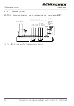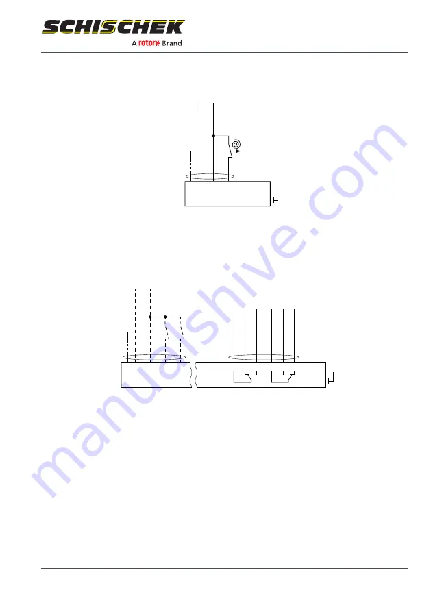
3.7.2.6.2 2-wire with spring return constant spring-return period F3
24...240 VAC/DC
~
~
–
+
PE
a
1
2
3
PA
Fig.
68: SB2.4 - cable type 3+PE, cable diameter 6
mm
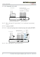
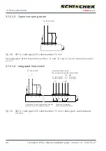
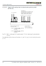
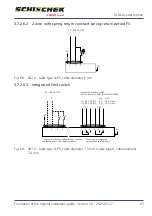
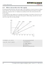
3.7.2.6.3 Integrated limit switch
Integrated auxiliary switch,
fuse on power supply side recommended.
Connection of drive unit depending on type and
application as per circuit diagrams above
Connection of integrated,
potential-free auxiliary switch
24...240 VAC/DC
~
~
–
+
PE
1
2
3
4
PA
a
b
1
2
3
4
5
6
< 5°
> 85°
U < 90 V AC/DC
U > 90 V AC/DC
2 A 10 A, slow
5 A 10 A, slow
min. max.
Fig.
69: SB3.0 - cable type 5+PE, cable diameter 7.5
mm / cable type 6, cable diameter
7.4
mm
3 | Device description
Translation of the original installation guide · Version 1.0 · 2021-05-27
55

