background image


Installation Manual


15 

Keypad Connection 

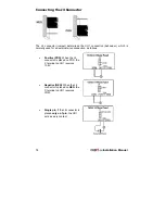
The ORBIT-14 can support up to five keypads. Each keypad consists of five wires 
and three terminal blocks (for the connection of zones 7 and 8). 

NOTE: 

The three terminal blocks are not applicable in a 6

-

LED keypad.  

1.  Connect four wires (Red, Black, Yellow, Green) from the keypad to the 

appropriate terminals on the main panel, according to the wire colours. 

2.  Each keypad has an additional white wire for the connection of a panic button. To 

connect the panic button, use the white wire as (+) and the black wire as (-). 

NOTE: 

The maximum distance between the panic button and the keypad is 30 meters. 

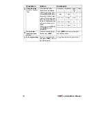
3.  Connecting zones 7 and 8: Zones 7 and 8, which are located on the keypads 

(except for the 6-LED keypad), are end-of-line supervised. If more than one 
keypad is connected to the system and zones 7 or 8 are used, the same zones in 
the other keypads must be shorted. Each zone can be used only once, in one of 
the keypads. 

NOTE: 

The short of a parallel zone must be done before powering the system

.


Connecting the J3 SIG IN Connector (Signal in Voice 
Mail) 

The J3 SIG IN voice connector enables the transfer of audio data between the Voice 
module and the phone line. For further instruction on the voice module, refer to the 
“Voice Module” documentation supplied with the product.  

Содержание ORBiT-14

Страница 1: ...Installation Manual...

Страница 2: ...r any other purpose disclosed to any person or firm or reproduced by any means electronic or mechanical without the express prior written permission of Rokonet Electronics Ltd The text and graphics ar...

Страница 3: ...vised of your right to file a compliant with the FCC if it is necessary 5 The telephone company may make changes in its facilities equipment operations or procedures that could affect the operation of...

Страница 4: ...dance with the instructions may cause harmful interference to radio communications However there is no guarantee that interference will not occur in a particular installation If this equipment does ca...

Страница 5: ...luded in following standards Standard 5 1999 EC Article Note EN 60950 00 3 1 a 1 EN 301 489 3 v 1 2 1 3 1 b 1 EN 50130 4 95 A1 98 3 1 b 1 TBR21 98 ETSI EG 201 121 v 1 1 3 2 Note 1 Full Orbit 14 system...

Страница 6: ...Installation Manual vi...

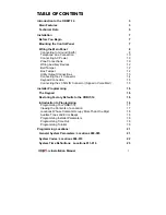
Страница 7: ...onnector 14 Keypad Connection 15 Connecting the J3 SIG IN Connector Signal in Voice Mail 15 Installer Programming 16 The Keypad 16 Restoring Factory Defaults to the ORBIT 14 16 Introduction to Program...

Страница 8: ...otocols Location 054 34 Automatic Central Station Protocols Location 055 36 Upload Download Rings Location 056 37 Swinger Shutdown Limit Location 057 37 System Controls Locations 059 060 38 Sub Instal...

Страница 9: ...o possible through the use of Rokonet s Upload Download software Main Features Zones 14 Programmable Intrusion Zones 12 zones on main board using zone doubling 2 zones on keypad 3 Keypad Emergency Zon...

Страница 10: ...istor Keypad Tamper Wall cover Automatic Arming Daily automatic arming Orbit 14 Main Panel Types P N Description RP214MA0000A Orbit 14 Main Panel Telephone impedance 600 Complies with FCC Part 68 regu...

Страница 11: ...typical 30 mA maximum 18 mA typical 37 mA maximum 75mA maximum Control panel connections 4 wire up to 300 ft 100 m from panel 4 wire up to 300 ft 100 m from panel 4 wire up to 300 ft 100 m from panel...

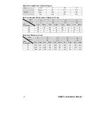
Страница 12: ...mA Feet Meter Feet Meter Feet Meter Feet Meter 100 780 238 625 190 495 151 310 95 300 260 79 208 64 165 50 103 32 650 120 37 96 30 76 23 48 15 Detectors Distance in Feet 18 19 20 22 24 1 0 9 0 8 0 6...

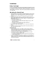
Страница 13: ...tions to devices requiring Uninterrupted Auxiliary Power e g PIRs Glass Break Detectors Connections to Smoke Detectors requiring Reset table Power Connections to any External Sounders 3 Have a Standby...

Страница 14: ...y charging circuit however prolonged improper connection of the battery to the control panel results in damage Power should remain disconnected until all connections have been made and checked for acc...

Страница 15: ...or static discharge experience permanent or general malfunctions The ideal ground is considered to be a unified earth ground in which an 8 foot copper clad rod located close to the existing power and...

Страница 16: ...is bent If in doubt you may want to enlist the help of a licensed electrician Telephone Line Connection These lines are typically derived from an installed RJ31X jack To connect telephone lines 1 Con...

Страница 17: ...ones on one input Use the following diagram for appropriate connection The tamper alarm will be the same for both of the zones 3 32K 2 21K 5 62K Tamper N C Alarm N C Tamper N C Alarm N C Zone No 1 Zon...

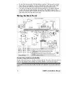
Страница 18: ...tage due to current requirements and distances involved make sure to use the appropriate wire gauge If the auxiliary outputs are overloaded exceed 600mA and are shut down you must disconnect all loads...

Страница 19: ...he 12V power to the smoke detector is supplied via the UO see page 8 The UO should be defined as AUX switch see page 31 Connecting the Utility Output Expansion Module If more than three UOs are requir...

Страница 20: ...is normally used for an external siren connection as follows Positive POS When the J4 connector is placed on POS the C terminal on UO1 receives 13 8V Negative NEG When the J4 connector is placed on NE...

Страница 21: ...NOTE The maximum distance between the panic button and the keypad is 30 meters 3 Connecting zones 7 and 8 Zones 7 and 8 which are located on the keypads except for the 6 LED keypad are end of line sup...

Страница 22: ...esponding pins Refer to page 8 4 Reapply power AC and or Standby Battery to the PC Board 5 After a short beep is heard remove the J1 jumper The ORBIT 14 s default settings are now restored 6 Check tha...

Страница 23: ...RP214USB000A USB RS232 Bus Adapter Remote ORBIT UD Remote U D Windows version from a personal computer The software and applicable modem with configured access to a telephone line must be installed C...

Страница 24: ...Used to display the next digit in a location containing at least two digits For example if 5 6 7 8 is stored in a location the 5 is displayed first when you press the 6 will be displayed Continue this...

Страница 25: ...To help acquaint you with some programming basics a short tutorial has been prepared It involves changing the Installer Code from the factory default of 0 2 1 4 to a sequence of your own choosing If...

Страница 26: ...bserve the Zone LEDs Press STAY STAY to advance to the next digit Once all four digits have been displayed attempts to view an additional digit will result in three error beeps If desired press STAY a...

Страница 27: ...ot have permission to change the following Central Station parameters from the Upload Download software Installer Code MS phone numbers the MS Lock Code and the Default Enable jumper It is NOT necessa...

Страница 28: ...with less than four digits For example for account number 123 enter 0123 In this case the ORBIT 14 will not send the 0 digit to the Central Station To use an account number with 0 digit for example 1...

Страница 29: ...l User Codes To set the system s internal clock To perform certain system functions and tests NOTE The Master Code cannot be seen by the installer through the zone LEDs on the keypad System Time Defin...

Страница 30: ...indicated time will defer the test transmission until the indicated periodic test time on the following day Location 016 Periodic Test Interval Default 00 Sets the interval for periodic test reportin...

Страница 31: ...oid an intrusion alarm however the zone must be secured before the expiration of the Exit Delay period Location 11 6 Entry Follower Usually assigned to motion detectors and to interior doors protectin...

Страница 32: ...buzzers simultaneously 5 Bell When Armed Buzzer When Disarmed Related to 24H zones If an alarm occurs in disarm mode the keypad s buzzer will be activated If an alarm occurs in arm mode the external B...

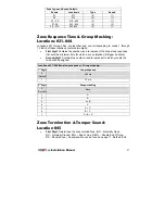
Страница 33: ...s loop response that sets the minimum time for which a zone violation will trigger an alarm Second digit Contains the number used to represent to which group s the zone will be assigned Locations 031...

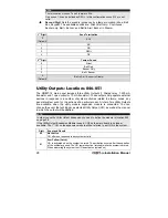
Страница 34: ...to a number of system activities related to alarms zones any general system event or the actions of a particular user A total of six Utility Outputs are available when the utility module expansion mo...

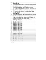
Страница 35: ...any type of alarm i e intrusion fire keypad initiated panic 06 Zone 1 Alarm Follow Latched UO is immediately activated when an alarm occurs on Zone 1 UO remains active latched for the duration of the...

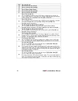
Страница 36: ...Fire Keying Follow Latched UO is activated immediately when a Fire alarm is triggered by a violation of zone 5 defined as Fire or by pressing the keypad s 4 and 5 keys simultaneously for two seconds...

Страница 37: ...to a lack of power from the commercial AC UO is deactivated when the system is operating properly from commercial AC power 2E AC Loss Follow Pulse UO is activated for several seconds and is then deact...

Страница 38: ...low you define the communication format as defined by the Central Station CS Dialler Control 1 Location 052 First digit Determines the number corresponding to the Dialling Method Duty Cycle and Centra...

Страница 39: ...in the standard manner Yes Enables Follow Me communication In addition to reporting to the Central Station the ORBIT 14 has a Follow Me feature in which a standard phone call is made to a designated p...

Страница 40: ...le 2 The dialler waits for a dial tone before it starts dialling Location 053 Dialler Controls 2 2nd Digit 2 nd Digit Wait for Dial Tone Telephone Connection and Supervision 0 No No 1 No Yes 2 Yes No...

Страница 41: ...00 Hz 1 33 pulses sec 390 ms 1800 Hz 2 20 pulses sec 390 ms 1800 Hz 3 10 pulses sec 390 ms 1800 Hz 4 40 pulses sec 650 ms 1800 Hz 5 33 pulses sec 650 ms 1800 Hz 6 20 pulses sec 650 ms 1800 Hz 7 10 pul...

Страница 42: ...00 Hz Dual round 390 40 Radionics Extended 40 2300Hz Dual round 390 50 Radionics 40 1400 Hz Parity 390 20 Radionics 40 2300Hz Parity 390 30 Radionics Extended 40 1400 Hz Parity 390 60 Radionics Extend...

Страница 43: ...e place Location 056 Number of Rings Default 08 Choose a number of rings greater than that which the customer will normally wait to answer an incoming call Enter the number of rings between 00 15 NOTE...

Страница 44: ...ring a valid User Code No Zone bypassing is NOT permitted Loudspeaker If the external sounder s is NOT equipped with a built in sound driver doing so causes the ORBIT 14 to produce an oscillating freq...

Страница 45: ...r No Yes No B Loudspeaker No Yes Yes C Loudspeaker Yes No No D Loudspeaker Yes No Yes E Loudspeaker Yes Yes No F Loudspeaker Yes Yes Yes Location 059 System Controls 1 2nd Digit 2 nd Digit Voice Modul...

Страница 46: ...en zone during auto arming will be bypassed and the system will be armed UO arm follow Pulsed or Latched UO will be activated after the Exit Delay time AC loss report and UO follow AC loss will be act...

Страница 47: ...2 nd Digit Alarm Restore Auto Arm Pre Warning 0 BTO No 1 Default BTO Yes 2 Zone Restore NO 3 Zone Restore Yes Sub Installer Restriction Level Location 061 The Sub Installer can be defined with two di...

Страница 48: ...ne 10 Alarm Reporting code 2 00 072 Zone 11 Alarm Reporting code 2 00 073 Zone 12 Alarm Reporting code 2 00 074 Zone 13 Alarm Reporting code 2 00 075 Zone 14 Alarm Reporting code 2 00 076 Keypad Fire...

Страница 49: ...y Restoral Code 2 00 103 Restore tamper from zones 1 9 2 00 104 Restore tamper from zones 2 10 2 00 105 Restore tamper from zones 3 11 2 00 106 Restore tamper from zones 4 12 2 00 107 Restore tamper f...

Страница 50: ...sarm Reporting code by master code quick arm key switch or remote arming 2 00 135 User 1 disarm Reporting code 2 00 136 User 2 disarm Reporting code 2 00 137 User 3 disarm Reporting code 2 00 138 User...

Страница 51: ...st 15 min 2 00 157 Fire zone trouble 2 00 158 Bell Loop Interrupted 2 00 159 Clock not set 2 00 160 Phone line cut 2 00 161 Day zone trouble 2 00 162 Low Battery restore 2 00 163 Loss of AC Power rest...

Страница 52: ...Dialler Control 2 012 Entry Delay 054 MS Pulsed protocol 013 Bell Cutoff Time 055 MS Auto protocol 014 Bell Delay 056 U D Rings 015 Periodic test time 057 Swinger Shut down 016 Periodic test interval...

Страница 53: ...User 12 Disarm 104 Tamp zone 2 10 restore 147 User 13 Disarm 105 Tamp zone 3 11 restore 148 User 14 Disarm 106 Tamp zone 4 12 restore 149 User 15 Disarm 107 Tamp zone 5 13 restore 150 User 16 Disarm...

Страница 54: ...12 KA Heat Zone Restore 12 114 13 KH Duct Zone Alarm Restore 14 116 Flame Zone Alarm Restore 15 117 Panic Zone Alarm Restore Silent Alarm 16 122 Audible Alarm 17 123 Perimeter Zone Alarm Restore 18 13...

Страница 55: ...Restore 46 120 47 PH Duress Alarm 48 121 48 HA Duress Restore 48 121 49 HH Troubles AC Trouble 5A 301 5A AT AC Restore 5A 301 51 AR Low Battery Trouble 52 302 52 YT Low Battery Restore 52 302 53 YR M...

Страница 56: ...el 5 2 Master Code 2 digit User Number to be set changed Authority Level No 0 User 1 User Un Bypass 2 Maid 3 Service Set Date 6 1 Master Code MM DD YY Set Time 6 2 Master Code HH MM Set Auto Arm Time...

Страница 57: ...Notes...

Страница 58: ...Notes...

Страница 59: ...rtation charges or costs of installation or any liability for direct indirect or consequential damages or delay Seller does not represent that its product may not be compromised or circumvented that t...

Страница 60: ...llowing telephone and fax numbers USA Tel 1 305 592 3820 Fax 1 305 592 3825 United Kingdom Tel 44 1527 576 765 Fax 44 1527 576 816 Italy Tel 39 02 392 5354 Fax 39 02 392 5131 Israel Tel 972 3 9616555...

Отзывы: