background image

Cascade Installation Guide 


23

4.


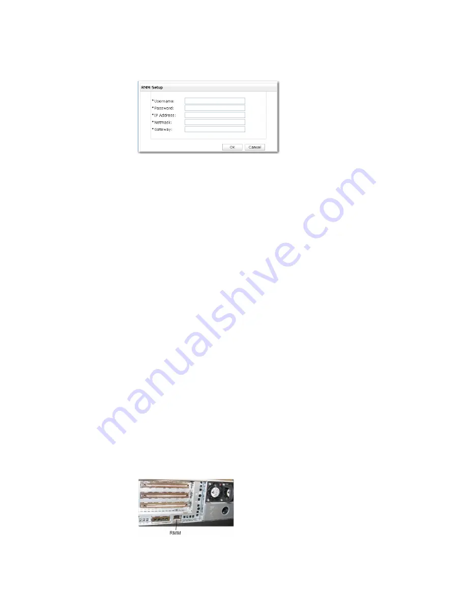
In the 

RMM Settings

 section, click 

Set up RMM

. This opens a setup 

page. 


5.


Enter the factory preset username 

admin

 and password 

password

 in the 

setup popup.  

6.


Enter the RMM network interface IP address, netmask and gateway and 
click 

OK

7.


Check to ensure that the new RMM address information is displayed in the 

RMM Settings

 section. 

8.


At the bottom of the 

Setup

 page, there is a checkbox labeled 

Power down 

after configuration

. This is provided for situations in which someone 

configures the Enterprise Profiler in a staging area and then subsequently 
moves it to another area.  


If the Profiler is mounted in the rack and connected to the network on 
which you will be using it, leave the 

Power down after configuration


box unselected and click 

Configure Now


If the Profiler must be powered off, remounted, and reconnected 
before it is deployed, select the 

Power down after configuration

 box 

and click 

Configure Now

9.


When you click 

Configure Now

, you will be prompted to change the 

password. The password you enter here must be the one you will use after 
this point in the procedure. Enter your new password. 

Configuring Remote Management Modules 

To configure the RMMs in the Database Module and Expansion Modules, 

1.


Disconnect the laptop you used to configure the Management Module 
from the network. 

2.


Using a crossover cable, connect it to the RMM connector on the Database 
Module. 


Содержание Cascade Express

Страница 1: ...Cascade Installation Guide Version 9 0 February 2011 ...

Страница 2: ...is Copyright 1998 Massachusetts Institute of Technology libpq is 1 Copyright 1996 2004 The PostgreSQL Global Development Group and 2 Copyright 1994 the Regents of the University of California Yahoo is Copyright 2006 Yahoo Inc pd4ml is Copyright 2004 2008 zefer org Rapid7 is Copyright 2001 2008 Rapid7 LLC CmdTool2 is Copyright 2008 Intel Corporation QLogic is Copyright 2003 2006 QLogic Corporation ...

Страница 3: ...s software is based in part on the work of the Independent JPEG Group This software is based in part on the work of the FreeType team This manual is for informational purposes only Addresses shown in screen captures were generated randomly by simulation software and used only on an internal network They are for illustrative purposes only and are not intended to represent any real traffic involving...

Страница 4: ...iv 712 00058 07 ...

Страница 5: ...Communication between Cascade appliances 5 Access to other network services 6 Access to traffic flow data Express and Gateway 6 Access to forwarding destinations Gateway only 6 3 Mounting and powering 7 Safety information 7 Hardware installation 7 4 Standard Profiler installation 8 Configuration information 8 Configuring the Standard Profiler 10 Network connections 13 Additional configuration 14 V...

Страница 6: ...e Express 31 Network connections 35 Additional configuration 36 Verification 37 Verifying Express operation 37 Verifying Remote Management Module access 41 Exiting the installation process 41 7 Sensor installation 42 Configuration information 42 Configuring the Sensor 44 Network connections 47 Additional configuration 48 Verification 49 Verifying Sensor operation 49 Verifying Remote Management Mod...

Страница 7: ...ation information 65 Configuring the Gateway 69 Network connections 71 Additional configuration 73 Identifying Profilers 73 Flow forwarding 73 Verification 74 Verifying Gateway operation 74 Verifying Remote Management Module access 75 Exiting the installation process 75 10 SAN installation 76 Introduction 76 Unpacking and inspection 76 Preparing to install the hardware 77 Card mounting considerati...

Страница 8: ...viii ...

Страница 9: ...ce must be provided to the Cascade appliance in order to verify the installation Therefore the most streamlined approach is to configure your data sources to send traffic data to the Cascade appliance as part of preparing to begin the installation The Preparations for Installation section of this guide discusses topics that should be considered before mounting and cabling the Cascade appliance Sec...

Страница 10: ...x ...

Страница 11: ... of the order are damaged or missing contact Riverbed Support 2 Preparations for installation Before installing the chassis ensure that the following considerations have been addressed Data sources Rack space Power Cooling Network connections Access to network Data sources The Cascade appliance must be receiving traffic information from at least one source in order for you to verify successful ins...

Страница 12: ...bed Steelhead appliance It monitors the LAN interfaces of the Steelhead appliance via the Riverbed Services Platform RSP The Sensor VE can also monitor traffic from taps or mirror ports on the monitored network using the Steelhead Aux port Gateway The Riverbed Cascade Gateway obtains traffic information from NetFlow IPFIX Packeteer FDR or sFlow sources Ensure that the Cascade appliance you are ins...

Страница 13: ...ort that must connect to a hub or switch on the management network The chassis management port is set by default for auto negotiation Ensure that a straight through cable to a hub or switch port on the management network is available at the rack location Ensure that the management network switch port is set to establish a connection at 100 or 1000 Mb s and full duplex Intermodule communication Ent...

Страница 14: ...de fiber with LC connectors Sensor configurations include 1 port copper 10 100 1000 Mbps RJ45 connector 2 port copper 10 100 1000 Mbps RJ45 connectors 2 port fiber 1 Gbps multimode fiber with LC connectors 2 port fiber 1 Gbps single mode fiber with LC connectors 2 port fiber 10 Gbps single mode fiber with LC connectors 2 port fiber 10 Gbps multimode fiber with LC connectors 4 port copper 10 100 10...

Страница 15: ...ts own web based user interface which you can access with a web browser The network address for the RMM does not need to be on the same subnet as the address for the Cascade appliance management interface The RMM has a 100baseTX port that must connect to a hub or switch on the management network The RMM port is set by default for auto negotiation Ensure that a straight through cable to a hub or sw...

Страница 16: ...ports If you will be using the Profiler or Express vulnerability scan feature then you must allow traffic on the port that the Cascade appliance is to use for accessing the vulnerability scanner server Obtain vulnerability scanner server addresses and port numbers from the administrator of those systems The default ports are as follows o Nessus 1241 o nCircle 443 o Rapid7 3780 o Qualys Requires ex...

Страница 17: ...e ready to mount the chassis in the rack 1 Locate the rails in the shipping carton 2 Locate the rail installation instructions in the accessory box 3 Mount the rails in the rack as described in the instructions 4 Place the chassis into the component mounting channels of the rails and ensure that the component release levers lock the chassis securely in the rails as described and illustrated in the...

Страница 18: ...tional during installation and can be specified afterwards on the Profiler Configuration General Settings page if necessary It may be useful to write the configuration values in the blank column of the table so that you can refer to them during the configuration step or afterward Profiler host name Profiler IP address Netmask Default gateway DNS name resolution for hosts enable or disable Primary ...

Страница 19: ...of hosts that the Profiler is to track individually The default values are 10 8 172 16 12 192 168 16 Security Profile settings You can use either three traffic collection profiles weekdays weeknights and weekends or four weekdays weeknights Saturdays and Sundays After installation you can define others You can also specify the times when weekdays begin and end default times are 9 00 am to 5 00 pm ...

Страница 20: ...ust have an Ethernet port configured for TCP IP networking It must also be running Mozilla Firefox or Microsoft Internet Explorer The LAN interface adapter settings of this PC must be set to IP Address 192 168 1 30 Network mask 255 255 255 0 Gateway 192 168 1 1 Using these settings connect to the Profiler as follows 1 Use a crossover Ethernet cable to connect the Ethernet port of your PC to the Ma...

Страница 21: ...Cascade Installation Guide 11 ...

Страница 22: ... the Power down after configuration box and click Configure Now 10 When you click Configure Now you will be prompted to change the password The password you enter here must be the one you will use after this point in the procedure Enter your new password 11 When the password change operation is completed exit from the browser session and disconnect the crossover cable from the Profiler Additional ...

Страница 23: ...nt connection can be on different subnets but these must correspond to the addresses you assigned for each interface on the Setup page 3 Point your browser to the Profiler IP address that you specified on the Setup page during the configuration task This displays the login page 4 Log in to the admin account with the password you specified at the end of the configuration task 5 Navigate to the Syst...

Страница 24: ...iguration pages For example you may want to set up security profile periods as early as possible The initial Setup page offers the choice of collecting separate traffic profiles for Weekdays weeknights and weekends or Weekdays weekends Saturdays and Sundays If you want to add more profiles or use a different profile scheme 1 Log in to the Profiler 2 Go to the Configuration Security Profiles page 3...

Страница 25: ...te the installation by 1 Verifying Profiler operation 2 Verifying that the Remote Management Module is accessible 3 Exiting the installation process Verifying Profiler operation Verify that the Profiler has been successfully installed and configured by making the following checks 1 Go to the Dashboard page and verify that the graphs display data ...

Страница 26: ...ation page and assure that all status indications System and Component DNS Server are displaying OK 3 Go to the System Devices Interfaces page and assure that each data source that is expected to be available is listed and that no status indicators are red ...

Страница 27: ...Installation Guide 17 4 Go to the Reports Traffic page Near the bottom of the Report Criteria section click Run now Verify that a traffic report is displayed It will take a short time for the report to display ...

Страница 28: ...M password and define additional RMM user accounts A successful login verifies accessibility to the remote management module Exiting the installation process After verifying that Profiler is receiving and reporting traffic data and its remote management module is accessible over the network ensure that the responsible person has the IP address login name and password of the Profiler and the RMM Th...

Страница 29: ...te the configuration values in the blank column of the table so that you can refer to them during the configuration step or afterward Profiler host name Profiler IP address Netmask Default gateway DNS name resolution for hosts enable or disable Primary DNS server IP address Secondary DNS IP address DNS search domain NTP server IP addresses Applies only if Profiler is being synchronized to an exter...

Страница 30: ...r alert notifications Inside addresses IP addresses or address ranges of hosts that the Profiler is to track individually The default values are 10 8 172 16 12 192 168 16 Security Profile settings You can use either three traffic collection profiles weekdays weeknights and weekends or four weekdays weeknights Saturdays and Sundays After installation you can define others You can also specify the t...

Страница 31: ...s Configuring the Management Module The first time you log in to a newly installed system it displays an initial Setup page This is a one time display After you set up the initial configuration you can make subsequent configuration changes on the Configuration pages of the GUI To configure the Enterprise Profiler you need a PC on the network to which you have connected the modules The PC must be r...

Страница 32: ...Cascade Installation Guide 22 3 Fill in all the required fields marked with an asterisk on the Setup page ...

Страница 33: ...area If the Profiler is mounted in the rack and connected to the network on which you will be using it leave the Power down after configuration box unselected and click Configure Now If the Profiler must be powered off remounted and reconnected before it is deployed select the Power down after configuration box and click Configure Now 9 When you click Configure Now you will be prompted to change t...

Страница 34: ...can be performed by logging in to the Profiler GUI and navigating to the Configuration pages For example the Setup page offers the choice of collecting separate traffic profiles for Weekdays weeknights and weekends or Weekdays weekends Saturdays and Sundays If you want to add more profiles or use a different profile scheme 1 Log in to the Profiler 2 Go to the Configuration Security Profiles page 3...

Страница 35: ...tion 2 Verifying that the Remote Management Modules are accessible 3 Exiting the installation process Verifying Profiler operation Verify that the Profiler has been successfully installed and configured by making the following checks 1 Go to the Dashboard page and verify that the graphs display data ...

Страница 36: ...Cascade Installation Guide 26 2 Go to the System Information page and assure that all status indications System Component and DNS Server are displaying OK ...

Страница 37: ...ria section click Run now Verify that a traffic report is displayed It will take a short time for the report to display Verifying Remote Management Module access Verify that the RMMs can be accessed as follows 1 On the network on which the RMMs are connected point your browser to the IP address that you specified for the Management Module RMM on the Setup page during the Configuration task For exa...

Страница 38: ...cessibility to the remote management module 5 Log in to each Expansion Module RMM to ensure that each is accessible over the network Exiting the installation process After verifying that the Enterprise Profiler is receiving and reporting traffic data and its remote management modules are accessible over the network ensure that the responsible person has the IP address login name and password of th...

Страница 39: ...r pages if necessary It may be useful to write the configuration values in the blank column of the table so that you can refer to them during the configuration step or afterward Express host name Express IP address Netmask Default gateway DNS name resolution for hosts enable or disable Primary DNS server IP address Secondary DNS server IP address DNS search domain Management interface port setting...

Страница 40: ...s receiving NetFlow data versions 1 5 7 or 9 or IPFIX data See Note 1 below sFlow port Applies only if Express is receiving sFlow data versions 2 4 or 5 See Note 1 below Packeteer port Applies only if Express is receiving Packeteer Flow Detail Records versions 1 or 2 See Note 1 below SNMP information Express is set by default to use SNMP Version 1 and the SNMP community name mazu all lowercase to ...

Страница 41: ...t Module gateway Service Management Leave this set to ByLocation unless you are requested to choose another group type for service locations Note 1 Do not send more than one type of flow data to the same port Configuring the Express The first time you log in to a newly installed system it displays an initial Setup page This is a one time display After you set up the initial configuration you can m...

Страница 42: ...ossover Ethernet cable to connect the Ethernet port of your PC to the Management connector on the left rear of the Express 2 Point your browser to https 192 168 1 10 This displays the login page 3 Log in with the default user name admin and the default password admin This displays the Setup page ...

Страница 43: ... 4 Fill in all the required fields marked with an asterisk on the Setup page 5 In the RMM Settings section click Set up RMM This opens a setup page 6 Enter the factory preset username admin and password password in the setup popup ...

Страница 44: ...ou click Configure Now you will be prompted to change the password The password you enter here must be the one you will use after this point in the procedure Enter your new password 11 When the password change operation is completed exit from the browser session and disconnect the crossover cable from the Express Additional configuration tasks such as specifying a traffic collection profile scheme...

Страница 45: ...p to Step 3 below If your Express is not a flow monitoring only model then connect the cables from the tap or mirror ports on the monitored networks to the network monitoring ports which are labeled Mon0 and Mon1 3 Connect a cable from the network to the RMM connector on the right rear of the Express The RMM connection and the Express management connection can be on different subnets but these mus...

Страница 46: ...annot be verified Set up at least one data source device preferably all data source devices and then perform the installation verification described in the Verification section below Additional configuration Additional configuration can be performed by logging in to the Express GUI and navigating to the Configuration pages For example you may want to set up security profile periods as early as pos...

Страница 47: ...tions of making other configuration changes refer to the Profiler help system Verification Complete the installation by 1 Verifying Express operation 2 Verifying that the Remote Management Module is accessible 3 Exiting the installation process Verifying Express operation Verify that the Express has been successfully installed and configured by making the following checks 1 Go to the Dashboard pag...

Страница 48: ...Cascade Installation Guide 38 ...

Страница 49: ...Cascade Installation Guide 39 2 Go to the System Information page and assure that all status indications System and Component DNS Server are displaying OK ...

Страница 50: ...e that each data source that is expected to be available is listed and that no status indicators are red 4 Go to the Reports Traffic page On the Hosts tab click Run now Verify that a traffic report is displayed It will take a short time for the query to run and the report to display ...

Страница 51: ...o the RMM you can change the default RMM password and define additional RMM user accounts A successful login verifies accessibility to the remote management module Exiting the installation process After verifying that Express is receiving and reporting traffic data and its remote management module is accessible over the network ensure that the responsible person has the IP address login name and p...

Страница 52: ...e if necessary It may be useful to write the configuration values in the blank column of the table so that you can refer to them during the configuration step or afterward Sensor host name Sensor IP address Netmask Default Gateway DNS name resolution for hosts enable or disable Primary DNS server IP address Secondary DNS server IP address DNS search domain Management interface port settings 10 100...

Страница 53: ...r faster installation use the default encryption certificate shipped with the Sensor and then generate a new certificate later SNMP information Sensor is set by default to use SNMP Version 1 and the SNMP community name mazu all lowercase to allow MIB browsing If you are configuring SNMP at this time obtain the necessary V1 or V3 information First Profiler data input address The address of the Prof...

Страница 54: ...is is a one time display After you set up the initial configuration you can make subsequent configuration changes on the Configuration pages of the GUI To configure the Sensor you need a separate PC and a crossover cable This PC must have an Ethernet port configured for TCP IP networking It must also be running Mozilla Firefox or Microsoft Internet Explorer The LAN interface adapter settings of th...

Страница 55: ... displays the login page 3 Log in with the default user name admin and the default password admin unless you arranged with Riverbed for a unique user name and password This displays the Sensor Setup page 4 Fill in all the required fields marked with an asterisk on the Setup page ...

Страница 56: ...work select the Power down after configuration box and click Configure Now 10 When you click Configure Now you will be prompted to change the password The password you enter here must be the one you use after this point in the procedure Enter your new password 11 When the password change operation is completed exit from the browser session and disconnect the crossover cable from the Sensor Additio...

Страница 57: ...connector that you used to configure the Sensor 2 Connect the cables from the taps or mirror ports on the monitored networks to the Sensor network monitoring ports which are labeled Mon0 Mon1 The number and type of monitor connectors depend on the Sensor model 3 Connect a cable from the network to the RMM connector on the right rear of the Sensor The RMM connection and the Sensor management connec...

Страница 58: ... password you specified at the end of the Configuration task 6 Navigate to the System Information page and confirm that the System status is OK Additional configuration Additional configuration such as specifying which Profilers are to receive data from the Sensor can be performed on the Configuration pages To specify Profilers that are to receive traffic data from the Sensor 1 Go to the Configura...

Страница 59: ...t the bottom of the page to apply the settings For descriptions of making other configuration changes refer to the Sensor online help system Verification Complete the installation by 1 Verifying Sensor operation 2 Verifying that the Remote Management Module is accessible 3 Exiting the installation process Verifying Sensor operation Verify that the Sensor has been successfully installed and configu...

Страница 60: ...n to the RMM you can change the default RMM password and define additional RMM user accounts A successful login verifies accessibility to the remote management module Exiting the installation process After verifying that the Sensor is receiving and reporting traffic data and its remote management module is accessible over the network ensure that the responsible person has the IP address login name...

Страница 61: ...n information 3 Ensure RSP is installed and enabled on the Steelhead 4 Download the Sensor VE package to the Steelhead upgrades only 5 Install Sensor VE in a RSP Package Slot 6 Configure and enable the slot 7 Configure the Sensor VE management interface 8 Configure the Sensor VE monitor interface 9 Complete the Sensor VE setup 10 Verify Sensor VE operation 11 Exit the installation process Prerequi...

Страница 62: ...nks configured This helps maintain consistency in interface reporting on the Cascade Profiler or Express that is receiving flow data from the Steelheads This setting may be impacted when you upgrade your Steelhead software Configuration information Information that is required to complete the installation is listed with an asterisk in the table that follows Items not marked with an asterisk can be...

Страница 63: ...use SNMP Version 1 and the SNMP community name mazu all lowercase to allow MIB browsing If you are configuring SNMP at this time obtain the necessary V1 or V3 information Profiler data input address The address to which the Sensor VE will send traffic data This is the IP address of the management interface of an Express or Standard Profiler or the address of the first Expansion Module for an Enter...

Страница 64: ...e Sensor VE package to the Steelhead upgrades only New Steelhead appliances that were ordered with the RSP option may include the Sensor VE package You can see if the Sensor VE package is already loaded by navigating to the Configure Branch Services RSP Packages page and looking in the Packages section If the Sensor VE package is already loaded skip to the next procedure Install Sensor VE in a RSP...

Страница 65: ...rom URL and enter the download URL from your purchase confirmation email 4 Download the Sensor VE package by clicking Add Package Note Do not navigate away from this page until the download completes Install Sensor VE in an RSP Package Slot 1 Go to the Configure Branch Services RSP Packages page 2 In the Slots section click an available slot number to expand the entry 3 Select Sensor VE package na...

Страница 66: ...ess to the network and is running with the correct memory limit 1 Go to the Configure Branch Services RSP Packages page 2 In the Slots section click the name or number for the slot in which the Sensor VE is installed This expands the entry 3 In the Memory Footprint field specify the number of megabytes of memory to be allocated to the Sensor VE as listed in the table below New Systems Memory Footp...

Страница 67: ..._0 must be copied to a corresponding Sensor VE monitor interface e g mon0 The Sensor VE must monitor traffic right at the start of the path at the LAN interface 1 Go to the Configure Branch Services RSP Data Flow page for the first Steelhead LAN to WAN data path For example navigate to Configure Branch Services RSP Data Flow inpath0_0 2 Click Add a VNI to expand the display 3 In the Interface list...

Страница 68: ...lick Apply to complete the assignment for this interface and close the details window 10 If the Steelhead has more than one LAN interface then repeat this procedure for each LAN interface For example navigate to Configure Branch Services RSP Data Flow inpath0_1 and continue with Step 2 above Configure the Sensor VE management interface Use RSP to specify the network address at which the Sensor VE ...

Страница 69: ...again 3 At the login prompt log in to the VMware component using the default account The password for this account is the same as the Steelhead CLI admin password The default password is password Login admin Password password 4 Click in the VMware window to launch the VMware Remote Console for the Sensor VE 5 Click in the Sensor VE console window to make it the active window Use Ctrl Alt to exit f...

Страница 70: ...he license key later if necessary but you must enter the IP address at this time The dialog will appear similar to the following 8 After answering the configuration questions confirm that the setup information is correct This causes the Sensor VE to reboot When the Sensor VE has finished rebooting you can close the remote console window Use Ctrl Alt to exit from the console window to your main win...

Страница 71: ...will be using the Sensor VE to monitor traffic from a network tap or mirror port such as a SPAN port on a switch or router then select the Monitor and collect traffic on the Steelhead Aux port option in the Monitor Interface Configuration section Otherwise this option should not be selected See the note below for additional requirements 5 When you click Configure Now you will be prompted to change...

Страница 72: ...de and then login in using the new password Additional configuration tasks can be performed by logging in to the Sensor VE from anywhere on the management network Note To use the Steelhead Aux port ensure that it is enabled on the Steelhead Go to the Steelhead Configure Networking Base Interfaces page and select Enable Aux Interface in the Auxiliary Interface section ...

Страница 73: ...vice to the Aux connector on the Steelhead chassis To monitor traffic via the Steelhead Aux port the Sensor VE must have this source enabled If you did not already enable it on the Setup page then you can enable it in the Monitor Interface Configuration section of the Sensor VE Configuration General Settings page Verify Sensor VE operation Verify that the Sensor VE has been successfully installed ...

Страница 74: ...ng traffic data ensure that the responsible person has the IP address login name and password This completes the installation process The Sensor VE can now be turned over to those who are responsible for setting up user accounts and operational parameters Refer to the online help system for further configuration procedures ...

Страница 75: ...s page if necessary It may be useful to write the configuration values in the blank column of the table so that you can refer to them during the configuration step or afterward Gateway host name Gateway IP address Netmask Default gateway DNS name resolution for hosts enable or disable Primary DNS server IP address Secondary DNS server IP address DNS search domain Management interface port settings...

Страница 76: ... are configuring SNMP at this time obtain the necessary V1 or V3 information First Profiler data input address The address of the Profiler to which the Gateway will send traffic data This is the IP address of the management interface of an Express or Standard Profiler or the address of the first Expansion Module mBlade 1 for an Enterprise Profiler If data sent to this Profiler is to be limited to ...

Страница 77: ...to be forwarded and whether or not the source address of the forwarded packets should be overwritten with the source address from which they were received If flow forwarding to this destination is to be limited to data received from only certain flow sources then specify those sources IP address Port Type Source Overwrite source address Yes No Data Forward Destination 2 IP address Port Type Source...

Страница 78: ...rce address Yes No Password to use for your initial Gateway login The default password admin New password to enter when prompted to change the initial Gateway password Applies only to systems not previously configured Remote Management Module IP address Remote Management Module netmask Remote Management Module gateway Note 1 Do not send more than one type of flow data to the same port ...

Страница 79: ...r Microsoft Internet Explorer The LAN interface adapter settings of this PC must be set to IP Address 192 168 1 30 Network mask 255 255 255 0 Gateway 192 168 1 1 Using these settings connect to the Gateway as follows 1 Use a crossover Ethernet cable to connect the Ethernet port of your PC to the Management connector on the left rear of the Gateway 2 Point your browser to https 192 168 1 10 This di...

Страница 80: ...5 In the RMM Settings section click Set up RMM This opens a setup page 6 Enter the factory preset username admin and password password in the setup popup 7 Enter the RMM network interface IP address netmask and gateway and click OK ...

Страница 81: ... session and disconnect the crossover cable from the Gateway Additional configuration such as specifying Profilers that are to receive data from the Gateway and forwarding flow data from particular sources to particular Profiler destinations can be performed by logging in to the Gateway GUI after it is connected to the management network If the Gateway is mounted in the rack and ready to connect t...

Страница 82: ...ets but these must correspond to the addresses you assigned for each interface on the Setup page 3 Point your browser to the IP address specified on the Setup page during the Configuration task This displays the login page 4 Log in to the admin account with the password you specified at the end of the Configuration task 5 Navigate to the System Information page 6 Confirm that the System status is ...

Страница 83: ...ess or Standard Profiler or the address of the first Expansion Module for an Enterprise Profiler 4 In the Flow Sources box either Leave the box blank to forward all flow data to the specified Profiler or Enter a comma separated list of the IP addresses of flow source devices whose traffic is to be sent to the Profiler You can enter IP addresses by clicking Browse and searching for the flow source ...

Страница 84: ...ose traffic is to be sent to the specified destination device You can enter IP addresses by clicking Browse and searching for the flow source device by name address or subnet 6 Click Configure Now at the bottom of the page to apply the settings The Gateway begins forwarding flow data to the destination devices within 5 minutes after you click Configure Now Verification Complete the installation by...

Страница 85: ...login page 2 Log in to the admin account with the default password password unless you arranged for the system to be shipped with a different password 3 While logged in to the RMM you can change the default RMM password and define additional RMM user accounts A successful login verifies accessibility to the remote management module Exiting the installation process After verifying that Gateway is r...

Страница 86: ...pport It is not necessary to configure the software at the time that the hardware is installed All other Profiler features will function normally without the software for the SAN interface being configured However the software must be configured and a SAN device connection must be available in order to verify the installation and operation of this option Installation involves the following steps 1...

Страница 87: ...hem before installing the card Cabling considerations The FC HBA card has two 4 Gbps Fibre Channel connectors The connectors are LC style for small form factor SFF multimode fiber optic cables They can be connected to a Fibre Channel switch or storage device over the following lengths of cable Speed 4 2 1 Gbps auto negotiated 50 125 μm fiber cable 62 5 125 μm fiber cable 4 2480 Gbps 150 meters 70 ...

Страница 88: ... fastening the top cover and remove the top cover 4 Remove the processor air duct plastic insert 5 Remove the PCI riser by lifting the two blue locking latches and then pulling the riser assembly straight up 6 Locate an empty full height PCI e slot in the PCI riser assembly 7 Insert the FC HBA card in the slot ensuring that it is seated properly 8 Reinstall the PCI riser assembly in its original p...

Страница 89: ... information is available before you begin the software configuration LUN _________________________________________________________ The SAN administrator must allocate a LUN logical unit number for Profiler to use Note that Profiler will reformat and partition its assigned storage area Any data on that LUN will be lost unless you specify a command option that prevents Profiler from copying its exi...

Страница 90: ...guring the software Contacting Riverbed Support Contact Riverbed Support to discuss and schedule the software configuration A Riverbed engineer will assist you in configuring the software and verifying that the installation is successful Also contact Riverbed Support if you would like Riverbed to perform the installation Phone United States and Canada 1 888 782 3822 Phone outside U S and Canada 1 ...

Страница 91: ......

Страница 92: ......

Отзывы: