8-4
CW-80 Checkweigher Installation/Service Manual
3.
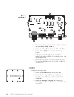
If serial communications are used, disconnect those wires from
the serial communications terminal (3).
4.
Using a hex-head socket wrench, remove the 4 standoffs (5).
5.
Remove the two phillips screws (4) from the remaining
corners.
6.
As the main board and display are joined together by a
soldered ribbon cable (6), gently lift both boards up away from
the head and set aside.
7.
Remove the white, plastic board support (7) from the edge of
the main board. Keep nearby, as you will need it for the first
installation step.
Installation
To install the new main board:
1.
Replace plastic board support at edge of main board.
2.
Reverse the above steps used for removing the board.
3.
Verify that all wire terminals correctly match the labeled
connections.
4.
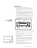
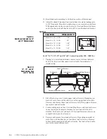
Replace the back plate by tightening the 10 screws in the
alternating pattern shown at left. Torque screws to a final value
of 15 in/lbs.
-EX
-SE
-SI
+SI
+SE +EX SHI
A
B
TxD
RxD
GND
T+
1
2
3
4
5
6
5
7
Figure 8-2.
Main CPU board
Back-panel screw tightening sequence.
Torque screws to final value of 15 in/lbs.
9
2
4
8
6
10
1
3
7
5


