background image

7-6

CW-80 Checkweigher Installation/Service Manual

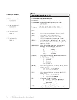
Table 7-3.

CCC (consolidated controls) output format

Non-continuous or continuous transmission

Print Formats:

Non-continuous—[STX][POL][DATA]<SP>[LB/KG/OZ]<SP>

[GR/NT]<EOL>

Continuous  — [STX][POL][DATA][L/K/O][G/N][ST]<EOL>

Where:

<STX>

is the ASCII “START OF TEXT” character (02 Hex).

[POL]

is the polarity indicator, 1 single character:
ASCII 20H (space) if positive weight reading.
ASCII 2DH (minus sign) if negative weight reading.

[DATA]

is a 7-character field including decimal point for weight
data. Data is right justified, with leading zeros padded left
with spaces (20 Hex).

[LB/KG/OZ/G]

is the 1- to 2-character indication of the current unit of
measure (for any PMODE setting except CNT):

KG

for kilograms

G

for grams

LB

for pounds

OZ

for ounces

<SP>

for lb and oz

[L/K/O/G]

is the 1-character indication of the current unit of measure
(for PMODE setting of CNT):

K

for kilograms

L

for pounds

O

for ounces

G

for grams

<SP> for lb and oz

[GR/NT]

is the 2-character indication of weight type (for any PMODE
setting except CNT):

GR

for Gross Weight information.

NT

for Net Weight information.

[G/N]

is the 1-character indication of weight type (for PMODE
setting of CNT):

G

for Gross Weight information.

N

for Net Weight information.

[ST]

is 1-character of status information:

M

for Motion, or scale is not in Standstill.

O

for scale Out of range, overloaded or
underloaded.

<SP> for in range, stable reading.

<EOL>

is either <CR> or <CR><LF>, depending on serial port
setting for End of Line Termination.

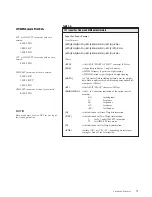
CCC Sample Print Outs

CCC Non-continuous Gross:

1.690 LB GR

CCC Non-continuous Net:

1.490 LB NT

CCC Continuous Gross:

1.690LG

CCC Continuous Net:

1.490LN

Содержание SURVIVOR CW-80

Страница 1: ...SURVIVOR CW 80 Checkweigher Installation Manual 32291...

Страница 2: ...rams 2 8 Power Up Sequence 2 9 3 Configuration 3 1 Before You Begin 3 1 Moving Around in the Menus 3 2 SETUP Menu chart 3 4 Menu Descriptions 3 6 4 Calibration 4 1 Overview 4 1 Calibration Procedure 4...

Страница 3: ...to Read and Write to IDs 6 20 7 Advanced Features 7 1 Bar Graph 7 1 Red Segments 2 7 1 Green Segment 1 7 2 Amber Segments 2 7 2 Setting Bar Graph Segments 7 2 Print Formats 7 3 8 Maintenance and Troub...

Страница 4: ...scale operator Overview The CW 80 Checkweigher is a high speed digital weight indicator and scale base programmed to compare weight readings with predetermined tolerance limits defining an ACCEPT band...

Страница 5: ...t Target and ID Annunciator lights for unit selection High intensity LED indicators for Over Under and Accept Display units in decimal lb kg oz lb and oz grams Stainless steel load cell for capacities...

Страница 6: ...ED alphanumeric display individual status indicators annunciator LED s and a membrane touch panel keypad encased in a watertight stainless steel case Take some time to familiarize yourself with the CW...

Страница 7: ...provided the conditions for standstill are met The Print Out parameter defines the format for printed information This key has secondary functions when using ID storage and when setting TARE OVER UND...

Страница 8: ...ET mode or when selecting an ID number pressing this key establishes a downward direction for modifying the value When in the Configuration mode the Down Arrow key moves down one level in the Configur...

Страница 9: ...emain in the OFF state scale motion must not have occurred within the last second A scale is In Motion when the current weight reading varies from the previous weight reading by more than the value of...

Страница 10: ...the acceptable weight band greatly under the rightmost red segment is used to indicate that the container weight is almost in the acceptable weight band but still under slightly under Illuminating bo...

Страница 11: ...umn 6 Turn the CW 80 Checkweigher upright and replace the platter on the platform 7 Attach the head to the column with the two bolts provided in the hardware kit If mounting the indicator head to the...

Страница 12: ...en wired to the indicator s CPU load cell terminal at the factory On units supplied with a column extra load cell cable is coiled inside the indicator head If a base and indicator head for remote moun...

Страница 13: ...rminal block wiring configurations Table 2 1 Serial Communications Port Pin EDP EDP Network RS 232 20 mA RS 485 Bidirectional Out Only Half Duplex Bidirectional T T GND GND GND GND RXD RXD TXD TXD B 4...

Страница 14: ...minal A ground wire is also required See Figure 2 3 and Table 2 1 on the previous page for more information on expanded serial communica tions Consider the following guidelines for an RS 485 interface...

Страница 15: ...otocol is as shown below STX RESPONSE CR ASCII 02 decimal Response commands from CW 80 ASCII 13 decimal character or CR LF 13 10 For example suppose you wish to send a remote command from an ASCII ter...

Страница 16: ...ty of AC or DC voltages in both normally open and normally closed models To operate equipment larger than 3 Amp draw larger isolation relays may be externally mounted and used in series with the on bo...

Страница 17: ...8 12 hours a separate AC recharging unit is available Quick connectors allow easy disconnection of the indicator power cable and connecting the battery charger in its place See Figure 2 5 The optiona...

Страница 18: ...Terminal 4 Configuration Setup Push Switch 5 Ribbon Cable to Power Supply Board 6 Ribbon Cable to Display Board EX SE SI SI SE EX SHI A B TxD RxD GND T 1 2 3 4 5 6 7 Figure 2 7 CPU board component sid...

Страница 19: ...is displayed 3 INITIALIZATION Init is displayed 4 0 0 Scale zeros weight allowable in Auto Zero Range setting if calibrated and in weighing mode or NO CAL No calibration message appears if scale is n...

Страница 20: ...water tight washer Fig 3 1 1 Removing the screw lets you operate the switch without opening the case To set up and calibrate the CW 80 you must be in the Configuration mode Remove the fillister screw...

Страница 21: ...2 as the parameter use the TARGET or ID keys to scroll to 2 PC When 2 PC is displayed use the OVER key to lock in 2 PC as the Zero Band setting See Figure 3 2 below TEST SETUP SERIAL STABLE Z BAND Z...

Страница 22: ...UNDER OVER UNDER OVER ACCEPT CW 80 Note Numeric Entry of Values Some menu items require a numeric entry In such a case you enter numeric values using the navigational keys as shown at right When a num...

Страница 23: ...PC FS 9 dd FS 1 dd FS 0 dd 3 0 dd 2 0 dd 1 0 dd 0 5 dd OFF 3 0 dd 2 0 dd 1 0 dd 0 5 dd 10 dd kg number g lb oz Load factor LF is in terms of of default unit grads OFF lb oz oz lb g kg Press ZERO key...

Страница 24: ...1 480 S 2 480 S 2 000 S 3 000 S 32 16 8 4 2 1 64 128 16 8 4 2 1 OFF 32 50 dd 20 dd 10 dd 5 dd 2 dd 1 dd same setting choices as Ptt SEt number number number grads number grads number grads number gra...

Страница 25: ...ations decimal point settings and Count By display resolution from the DEFALT menu item For the default unit of measure the possible selections are oz lb g and kg The lb oz unit is not allowed as a st...

Страница 26: ...DIV 5 DIV 10 DIV 20 DIV 50 DIV 100 DIV 200 DIV 500 Decimal Point Position Allows you to place the decimal point position The CW 80 combines the settings of GRADS and CNT BY to display the default sca...

Страница 27: ...BAND See Z BAND definition Zero Threshold Allows you to select a threshold or reset point where automatic printing functions reset themselves to be retriggered In some cases it is not practical to hav...

Страница 28: ...storage but protects them from accidental overwrite Sleep Mode Defines when and if the CW 80 should change to a low power state to conserve power DELAY is the number of minutes the CW 80 will remain...

Страница 29: ...n UN 1 and OV 1 will be in the ACCEPT range All UN and OV values are set in grads dd and function as follows UN 1 Lower limit of ACCEPT band Number of grads from Target value until ACCEPT goes off and...

Страница 30: ...1 0 SEC 8 SEC 6 SEC 4 SEC 2 SEC 0 SEC 1 2 SEC 1 6 SEC 1 4 SEC 1 8 SEC 2 0 SEC RS 485 RS 232 OFF OFF ON OFF ON 19200 9600 4800 2400 1200 CR LF ON OFF Set address number with directional navigator keys...

Страница 31: ...t with little or no receive buffers End of Line Characters Selects how a line of data transmitted through the serial port ends It does not indicate which EOL termination to expect with incoming transm...

Страница 32: ...to a standstill again AP2 Configures the CW 80 to perform automatic transmission of serial data each time the scale settles out of motion on its transition from Start Up Zero When an object is placed...

Страница 33: ...is setting does not affect requests for status weight data tolerance values etc The Acknowledgment is defined as the following ASCII character sequence EOL where is ASCII 2A Hex EOL is the End of Line...

Страница 34: ...ys for numeric entry of the desired test weight While SPAN is displayed place test weight on scale and press ZERO key to activate span calibration The working display S CAL lasts for 10 seconds When c...

Страница 35: ...apacity weight value 3 If calibrating with test weight equal to full scale capacity press ZERO key SPAN is displayed If calibrating with test weight less than full scale capacity adjust number to your...

Страница 36: ...ale OU SET Over Under Set Allows the operator to digitally set the Accept band tolerance values using keypad buttons while in Normal Weighing mode PTT SET Push To Tolerance and Set Combination mode th...

Страница 37: ...perator in normal weighing mode and are in the default unit of weight All settings below the UNDER ACCEPT OVER display bar are made by the installer in Configuration mode and are in graduations NOTE G...

Страница 38: ...an be altered in a similar manner with the OVER key These altered Un 1 and Ov 1 values remain active until either the TARGET key is pressed again or the CW 80 is powered down UNDER OVER ACCEPT SLIGHTL...

Страница 39: ...TOLERANCE SET mode combines both methods acquired and digitally set for establishing the ACCEPT band The Un 1 value is first acquired as in PTT mode on previous page This acquired value can then be a...

Страница 40: ...er or the UNDER key to make it smaller 3 Digitally alter the displayed value using the ZERO UNITS PRINT and TARE keys Remember that these keys will alter the display only in the direction you establis...

Страница 41: ...TARE key reduces the value of the digit above it by 1 The least significant digit controlled by the TARE key is reduced by 5 which is the size of the display division Count By setting When a digit is...

Страница 42: ...od called Auto Rolling puts the display into a constantly increasing or decreasing mode which you can easily stop when your new desired value is reached The display rolls at a speed of 2 display divis...

Страница 43: ...ng This Tare Display Set mode lasts for 3 seconds unless a key is pressed which resets the 3 second time interval The CW 80 response is dependent on which key is pressed The OVER or UNDER keys Pressin...

Страница 44: ...N NEG g kg lb oz Net ID TARGET TARE ZERO UNITS PRINT T UNITS UNDER OVER CW 80 UNDER OVER ACCEPT NET ZERO MOTION NEG g kg lb oz Net ID TARGET TARE ZERO UNITS PRINT T UNITS UNDER OVER CW 80 UNDER OVER A...

Страница 45: ...of 1 Tare display 2 Set adjustment direc tion 3 Adjust value and 4 Timeout to overwrite existing tare and store new tare in memory The following example illustrates setting a tare value of 1 60 lbs NE...

Страница 46: ...ERO UNITS PRINT T UNITS UNDER OVER CW 80 UNDER OVER ACCEPT STEP 4 Press the UNITS key once to increment the digit above the key from 0 to 1 STEP 5 Allow 3 seconds for the unit to timeout and store 1 6...

Страница 47: ...r R ONLY the multiple ID storage feature is activated Any of 299 available ID registers can be selected Each ID number must have four distinct categories of information Over tolerance value Ov 1 Under...

Страница 48: ...n associated with ID 50 These values become the current Over Under Tare values The display units change to the unit of measure recalled for ID 50 register Display shows RECALL then returns to Normal W...

Страница 49: ...of weight the CW 80 will zero off in this manner is limited by the zero band ZbANd setting in the Setup menu Choices are 2 of full scale 2PC or 100 of full scale 100PC ZERO Test Mode number XXXXXXX T...

Страница 50: ...can manipulate Over Under Tare and Units values call up current settings for Tare Tolerance sets and perform reporting functions Also you can use special commands to transmit weight data directly from...

Страница 51: ...er 01 Hex Start of Header that is a preamble to all bidirectional serial commands ADDR HIGH is a single ASCII character for the most significant digit of the two digit Checkweigher Address ADDR LOW is...

Страница 52: ...eared by either a Y or H command No acknowledgement is made if transactions are in the buffer Only the transactions are transmitted If the transaction buffer is empty the CW 80 acknowledges the comman...

Страница 53: ...the Acknowledgement Character sequence EOL if enabled Note that the contents of the Target value of the current ID are unaffected by this command CO CLEAR OVER COMMAND This sequence requests the CW 8...

Страница 54: ...OVERS COMMAND XUA XMIT ALL UNDERS COMMAND XS XMIT STATUS COMMAND The XS command requests the CW 80 to transmit the current status CW 80 Response Format STX G N T L K O Z G M S O O A U EOL Where STX i...

Страница 55: ...ransmit the current ID register number The valid values are 0 299 There are 299 individual OVER UNDER TARE UNITS register sets that can be randomly accessed Response Format STX T nnn EOL Where STX is...

Страница 56: ...ding decimal point for Target value data when used in lb and oz mode Data is right justified with leading zeros padded left with spaces 20 Hex OZDATA is a two five character field dependent on scale c...

Страница 57: ...SCII character for space 20 Hex UNITS is the one two character indication of the current unit of measure kg for kilograms g for grams lb for pounds oz for ounces lb oz use special format See XTG comma...

Страница 58: ...value associated with the current ID number Response Format STX T nnn POL DATA SP UNITS EOL Where STX is the one ASCII character 02 Hex for Start of Text T is ASCII literal text 54 Hex nnn is the thr...

Страница 59: ...s the one ASCII character 02 Hex for Start of Text POL is the polarity or sign of the current displayed weight space 20 Hex for positive values 2D Hex for negative values DATA is a seven character fie...

Страница 60: ...r activated ACPT for ACCEPT Tolerance annunciator activated EOL is either CR or CR LF depending on serial port setting for End of Line Termination XTA XMIT ALL TARES COMMAND This sequence requests the...

Страница 61: ...pounds oz for ounces lb oz use special format See XTG command for full details EOL is either CR or CR LF depending on serial port setting for End of Line Termination XTGA XMIT ALL TARGETS COMMAND Thi...

Страница 62: ...ermination XOA XMIT ALL OVERS COMMAND This sequence requests the CW 80 to transmit a list of all stored Over values by ID number Only valid over values will be transmitted Response Format STX O 001 PO...

Страница 63: ...is the one ASCII character 02 Hex for Start of Text U is ASCII literal text 55 Hex nnn is the three ASCII character for the ID number Example nnn would be 025 for the 25th ID register is ASCII litera...

Страница 64: ...CII character for the most significant digit of the two digit CW 80 Address ADDR LOW This is a single ASCII character for the least significant digit of the two digit CW 80 Address COMMAND This is a t...

Страница 65: ...mat STX T nnn POL DATA SP UNITS EOL Where STX is the 1 ASCII character 02 Hex for Start of Text T is ASCII literal text 54 Hex nnn is the 3 ASCII character for the ID number ex nnn would be 025 for th...

Страница 66: ...for negative values DATA is a 7 character field with including decimal point for Target value data Data is right justified with leading zeros padded left with spaces 20 Hex SP is the ASCII character...

Страница 67: ...ne Termination XU XMIT UNDER COMMAND This sequence requests the CW 80 to Transmit the Under value associated with the ID number located in the Location character field It does not make this Under valu...

Страница 68: ...s when successful with the Acknowledgement Character sequence EOL if enabled CTG CLEAR TARGET COMMAND This sequence requests the CW 80 to Clear the Target value associated with the ID specified in the...

Страница 69: ...in the designated ID This is the ASCII Character 2C Hex ID This is a 3 character field that specifies the record number or location of the ID where the OVER UNDER TARE UNITS data is to be stored Under...

Страница 70: ...he newly entered parameters the current checkweigher parameters The entry of Tare Tolerance parameters into ID 000 immediately changes the Checkweigher s current operational parmeters but ID 000 is no...

Страница 71: ...e OVER UNDER TARE UNITS data is to be stored This is the ASCII Character 2C Hex Under Data This is an eight character field including sign and decimal point that represents the Under Value associated...

Страница 72: ...IS IN THE FOLLOWING FORMAT Response Format STX ID sp empty EOL Where STX This is a single ASCII character 02 Hex Start of Text that is a preamble to all bidirectional serial command responses ID This...

Страница 73: ...termining if a container is too heavy Over too light Under or in a correct range ACCEPT The functions of the 5 LEDs or segments are described in the following paragraphs Red Segments 2 The red segment...

Страница 74: ...nfiguration mode or can be set by the operator in Normal Weighing mode When the weight on the scale just exceeds the ACCEPT band by 1 display division the first amber segment lights This level is set...

Страница 75: ...7 1 TOL tolerance output format Units kg g lb oz see following page for lb and oz units print format Print Format STX POL DATA SP KG G LB OZ SP GR NT O U ST EOL Where STX is the ASCII START OF TEXT ch...

Страница 76: ...in lb and oz mode Leading 0 s to be transmit ted as spaces 20 Hex DATAOZ 2 to 5 character field dependent on scale capacity including decimal point for ounce weight in lb and oz weighing mode Data is...

Страница 77: ...or weight data Data is right justified with leading zeros padded left with spaces 20 Hex L K O G is the 1 character indication of the current unit of measure K for kilograms G for grams L for pounds O...

Страница 78: ...rams G for grams LB for pounds OZ for ounces SP for lb and oz L K O G is the 1 character indication of the current unit of measure for PMODE setting of CNT K for kilograms L for pounds O for ounces G...

Страница 79: ...LB KG OZ G is the 1 to 2 character indication of the current unit of measure KG for kilograms G for grams LB for pounds OZ for ounces SP for lb and oz G is the indication for Gross Weight information...

Страница 80: ...ID number must be a positive integer Configuration settings relating to scale capacity divisions grads ordecimalpt havebeenchanged Recalibrate scale using current settings No tolerances have been ente...

Страница 81: ...v r e S y a l p s i d t h g i e w c i t a r r E e l a c s r a e n n o i t a r b i V r o n o i t a r b i v f o e c r u o s e v o m e R r o t a c i d n i f o g n i g a r e v a l a t i g i d t s u j d a...

Страница 82: ...y lift power board from the main board display standoffs and set aside B To remove the main board display 1 Remove the 10 pin display ribbon cable from the main board See Figure 8 2 1 on following pag...

Страница 83: ...pport 7 from the edge of the main board Keep nearby as you will need it for the first installation step Installation To install the new main board 1 Replace plastic board support at edge of main board...

Страница 84: ...ow be removed from scale Do not lose shim beneath load cell 5 Thread cable of replacement load cell through rubber grommet Position load cell on shim and screw in two lower load cell screws Torque to...

Страница 85: ...om indicator remove rear cover from indicator head 10 screws and disconnect load cell cable from indicator s terminal strip 2 Lift off scale top cover Locate upper load cell screws Depending on model...

Страница 86: ...ere cable enters indicator head 9 Reattach rear cover by tightening screws in an alternating pattern to a final torque value of 15 in lbs 10 Recalibrate scale according to Calibration section of this...

Страница 87: ...igital Specifications Digital Filter Software selectable 1 2 4 8 16 32 64 128 Digital Outputs 3 optional 5 VDC TTL level digital outputs to indicate Over Under and Accept status Optional relays availa...

Страница 88: ...nclosure Enclosure Materials 304 stainless steel Mechanical Capacities Available 6 lb 6 x 002 lb 96 x 05 oz 3 x 001 kg 3 000 x 1 g 10 lb 10 x 005 lb 160 x 1 oz 5 x 002 kg 5 000 x 2 g 15 lb 15 x 005 lb...

Страница 89: ...5 25 H 609 6 mm x 609 6 mm x 133 3 mm Column 18 H 457 2 mm Weights 6 10 15 30 lb 20 lb 9 07 kg 30 60 100 lb 23 lb 10 4 kg 100 200 300 500 1000 lb 78 lb 35 4 kg 200 300 500 1000 lb 95 lb 43 1 kg 200 3...

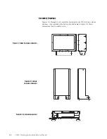
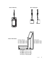
Страница 90: ...es 9 1 through 9 6 are assembly drawings for the CW 80 head column and base Also included is the battery box and charger Figure 9 6 shows dimensions for all available sizes Figure 9 1 Head rear and si...

Страница 91: ...n 24 max 24 platform 28 min 30 max min dimension indicator fully upright max dimension indicator fully tilted Overall height 12 column 19 max 18 column 25 max 24 column 31 max 30 column 37 max Package...

Страница 92: ...s 12 32144 Power supply board 115VAC w BBU charging circuit N C relays 12 32145 Power supply board 230VAC w BBU charging circuit N C relays 32149 32151 32415 32416 32717 13 14831 Screw MACH 4 40NC x 5...

Страница 93: ...back up unit 32387 Cable assembly battery backup box 15671 Cable grip 1 4 NPT battery backup box 31223 Relief valve battery backup box 30330 Enclosure battery backup box 30204 Standoff 1 4 20 x 1 156...

Страница 94: ...t Description 1 14951 Screw cap 1 4 28NF x 3 8 100 lb only 2 14920 Screw overload protection 8 32NC x 1 4 3 35128 Foot 1 4 20NC 4 14645 Jam nut foot 5 35066 Bottom subassembly 6 15220 Rivet sealing 7...

Страница 95: ...Appendix 9 9 TOP VIEW OF SCALE WITH COVER REMOVED 17 13 10 9 16 1 2 3 4 5 8 18 19 20 21 22 23 25 11 26 27 12 10 11 11 10 7 15 14 100 lb 12 x 12 only 24 10 x 10 and 12 x 12 Base Assemblies...

Страница 96: ...me top 18 x 24 14 49775 Frame top 24 x 24 RL1260 models 14 19114 Frame top 24 x 24 RL1250 model 15 15418 Grommet rubber 3 16 ID 16 15047 Screw set 1 2 20NF x 1 2 17 15409 Clamp nylon cable 18 15138 Wa...

Страница 97: ...9 11 18 x 18 18 x 24 and 24 x 24 Base Assemblies 27 4X 22 2X 19 9 8X 10 4X 26 4X 25 4X 17 18 14 21 23 15 16 24 1 4X 2 4X 3 4 5 2X 6 4X 20 4X 9 8X 12 SECTION A A TOP VIEW OF SCALE WITH COVER REMOVED 8...

Страница 98: ...8 Ctrl Y EM 25 19 Ctrl Z SUB 26 1A Ctrl ESC 27 1B Ctrl FS 28 1C Ctrl GS 29 1D Ctrl RS 30 1E Ctrl _ US 31 1F 128 80 129 81 130 82 131 83 132 84 a 133 85 134 86 135 87 136 88 137 89 e 138 8A 139 8B 140...

Страница 99: ...on 1 0 4 95 Original release Version 1 1 7 95 1 Numeric Display Blanking added 2 CR as well as CR LF allowed bidirectionally as commands Version 1 2 1 Keypad tactile sensitivity decreased Version 1 3...

Страница 100: ...exists and was not caused by accident misuse neglect alteration improper installation improper repair or improper testing RLWS shall be the sole judge of all alleged non conformities Such equipment h...

Отзывы: