Maintenance and Troubleshooting
8-7
5.
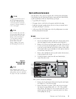
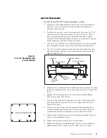
Thread cable of replacement load cell through rubber grommet. Position
bottom shim directly beneath load cell and screw in lower load cell
screws. Torque to 120 in. lbs for 18" x 18" and 24" x 24" scales.
6.
Turn scale right side up. Position spacer plate on load cell, then place
the top spider into position. Screw in four upper load cell screws.
Torque to 120 in. lbs for 18" x 18" and 24" x 24" scales.
7.
Connect load cell cable to correct pins on indicator terminal strip. See
Figure 2-2 in Installation section.
8.
Tighten cord grip where cable enters indicator head.
9.
Reattach rear cover by tightening screws in an alternating pattern to a
final torque value of 15 in/lbs.
10. Recalibrate scale according to Calibration section of this manual.
11. Adjust Overload Protection Screw on bottom of scale by loading scale
to 125% capacity. Place this weight on top cover, centered on platform.
With appropriate size hex wrench, screw in Overload Protection Screw
until it touches load cell, then back it off 1/6 turn. Recheck calibration.
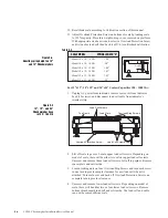
12. To reset corner Overload Stop Screws, load top spider over one corner
with 55%-60% of scale capacity. Adjust screw under that corner to just
touch top frame, then tighten locking nut if one is used. Repeat for each
corner. Replace top cover and re-level scale if necessary.


