Section 14 Watchdog Timer (WDT)
Rev. 1.00 Apr. 28, 2008 Page 398 of 994
REJ09B0452-0100
14.4 Operation
14.4.1
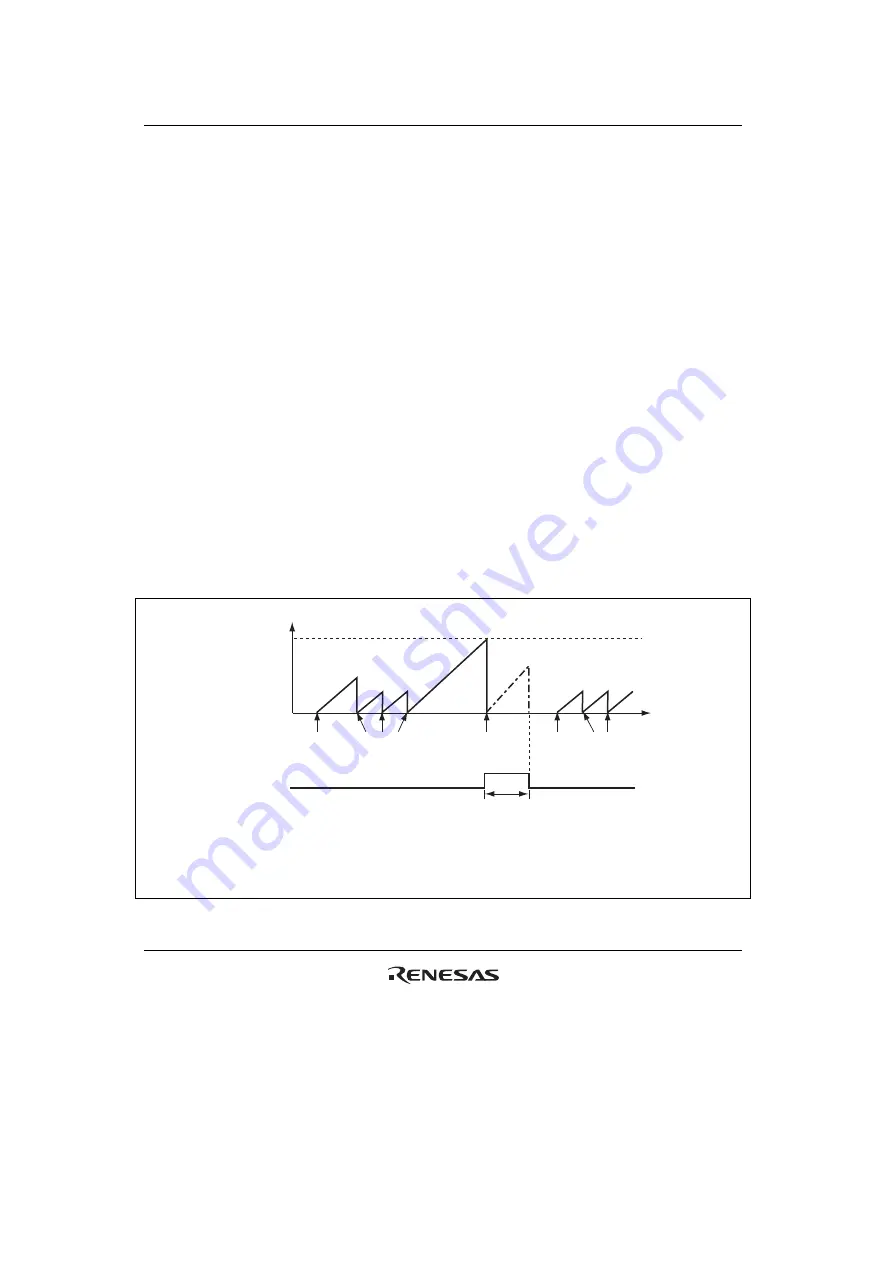
Watchdog Timer Mode
To use the WDT as a watchdog timer, set the WT/
IT
bit and the TME bit in TCSR to 1. While the
WDT is used as a watchdog timer, if TCNT overflows without being rewritten because of a
system malfunction or another error, an internal reset or NMI interrupt request is generated. TCNT
does not overflow while the system is operating normally. Software must prevent TCNT
overflows by rewriting the TCNT value (normally be writing H'00) before overflows occurs.
If the RST/
NMI
bit of TCSR is set to 1, when the TCNT overflows, an internal reset signal for this
LSI is issued for 518 system clocks as shown in figure 14.2. If the RST/
NMI
bit is cleared to 0,
when the TCNT overflows, an NMI interrupt request is generated.
An internal reset request from the watchdog timer and a reset input from the
RES
pin are
processed in the same vector. Reset source can be identified by the XRST bit status in SYSCR.
If a reset caused by a signal input to the
RES
pin occurs at the same time as a reset caused by a
WDT overflow, the
RES
pin reset has priority and the XRST bit in SYSCR is set to 1.
An NMI interrupt request from the watchdog timer and an interrupt request from the NMI pin are
processed in the same vector. Do not handle an NMI interrupt request from the watchdog timer
and an interrupt request from the NMI pin at the same time.
TCNT value
H'00
Time
H'FF
WT/
IT
= 1
TME = 1
Write H'00 to
TCNT
WT/
IT
= 1
TME = 1
Write H'00 to
TCNT
518 System clocks
Internal reset
signal
WT/
IT
:
TME:
OVF:
[Legned]
Overflow
OVF = 1
*
Timer mode select bit
Timer enable bit
Overflow flag
Note
*
After the OVF bit becomes 1, it is cleared to 0 by an internal reset.
The XRST bit is also cleared to 0.
Figure 14.2 Watchdog Timer Mode (RST/
NMI
= 1) Operation
Содержание H8S/2100 Series
Страница 2: ...Rev 1 00 Apr 28 2008 Page ii of xxvi...
Страница 54: ...Section 1 Overview Rev 1 00 Apr 28 2008 Page 28 of 994 REJ09B0452 0100...
Страница 92: ...Section 2 CPU Rev 1 00 Apr 28 2008 Page 66 of 994 REJ09B0452 0100...
Страница 158: ...Section 5 Interrupt Controller Rev 1 00 Apr 28 2008 Page 132 of 994 REJ09B0452 0100...
Страница 244: ...Section 8 8 Bit PWM Timer PWMU Rev 1 00 Apr 28 2008 Page 218 of 994 REJ09B0452 0100...
Страница 330: ...Section 10 16 Bit Timer Pulse Unit TPU Rev 1 00 Apr 28 2008 Page 304 of 994 REJ09B0452 0100...
Страница 354: ...Section 11 16 Bit Cycle Measurement Timer TCM Rev 1 00 Apr 28 2008 Page 328 of 994 REJ09B0452 0100...
Страница 380: ...Section 12 16 Bit Duty Period Measurement Timer TDP Rev 1 00 Apr 28 2008 Page 354 of 994 REJ09B0452 0100...
Страница 416: ...Section 13 8 Bit Timer TMR Rev 1 00 Apr 28 2008 Page 390 of 994 REJ09B0452 0100...
Страница 494: ...Section 15 Serial Communication Interface SCI Rev 1 00 Apr 28 2008 Page 468 of 994 REJ09B0452 0100...
Страница 612: ...Section 18 I 2 C Bus Interface IIC Rev 1 00 Apr 28 2008 Page 586 of 994 REJ09B0452 0100...
Страница 706: ...Section 20 LPC Interface LPC Rev 1 00 Apr 28 2008 Page 680 of 994 REJ09B0452 0100...
Страница 752: ...Section 21 FSI Interface Rev 1 00 Apr 28 2008 Page 726 of 994 REJ09B0452 0100...
Страница 774: ...Section 23 RAM Rev 1 00 Apr 28 2008 Page 748 of 994 REJ09B0452 0100...
Страница 1008: ...Section 28 Electrical Characteristics Rev 1 00 Apr 28 2008 Page 982 of 994 REJ09B0452 0100...
Страница 1020: ...Rev 1 00 Apr 28 2008 Page 994 of 994 REJ09B0452 0100...
Страница 1023: ......
Страница 1024: ...H8S 2117R Group Hardware Manual...


