21
ENGLISH
54
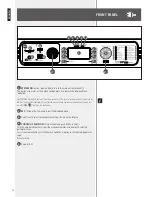
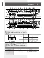
Power cord input (to be connected to a mains earthed socket only).
55
POWER
switch (0 = OFF, I = ON).
56
Input for 48 V dc power supply (removable screw terminals) through batteries.
N
OTe
:
accOrdiNg
TO
eN 54-16
STaNdard
,
The
backup
pOwer
SupplY
uNiT
Shall
be
iNSTalled
iNTO
The
SaMe
rack
cabiNeT
where
There
iS
The
audiO
SYSTeM
wiTh
eMergeNcY
purpOSeS
(
Or
a
SYSTeM
parT
)
TO
which
iT
iS
cONNecTed
.
T
he
deTecTiON
Of
48 V
dc
pOwer
SupplY
iNVOlVeS
The
iMpliciT
cONdiTiON
ThaT
The
SYSTeM
iS
alwaYS
TurNed
ON
,
ThuS
NOT
allOwiNg
ShuTdOwN
Of
The
MaiN
uNiT
ThrOugh
The
reSpecTiVe
fuNcTiON
iN
The
MeNu
,
NOr
ThrOugh
The
pOwer
SwiTch
55
.
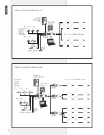
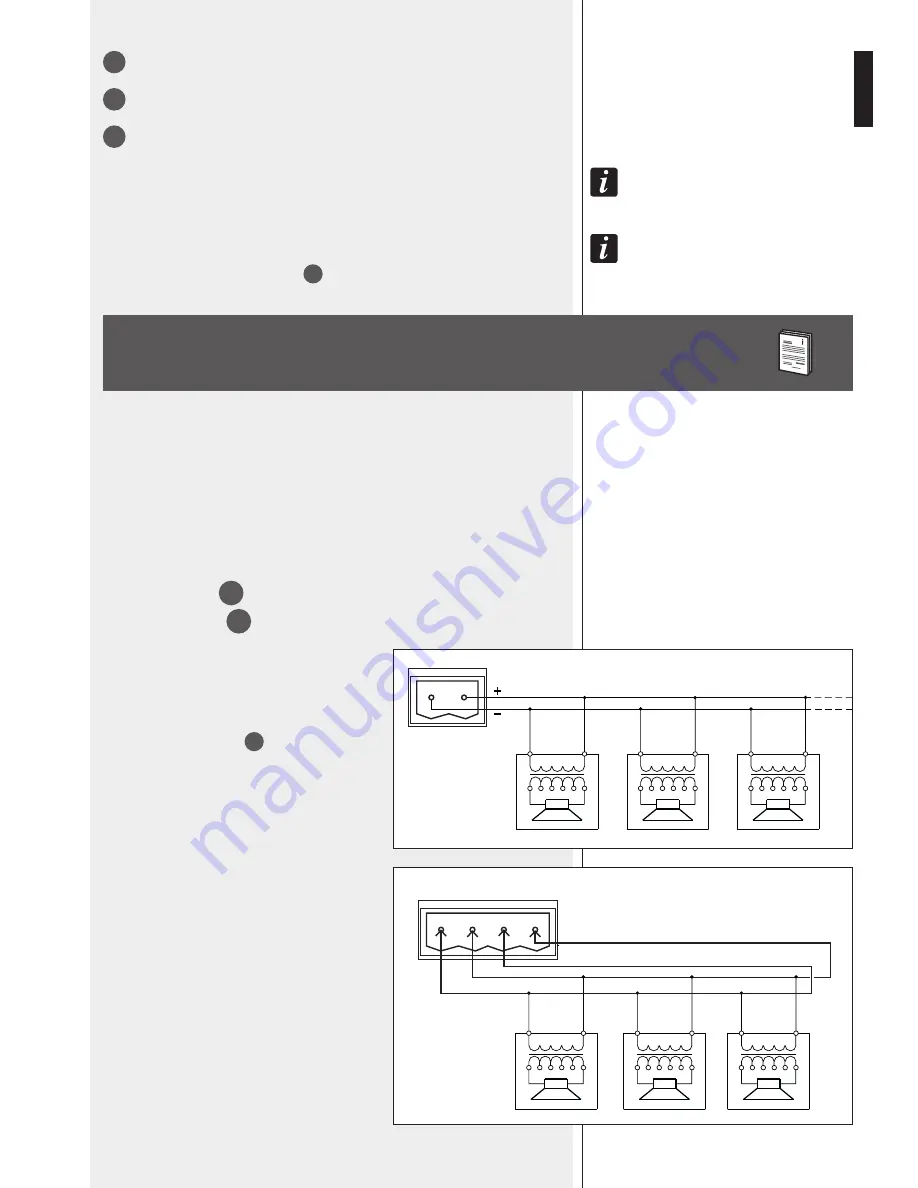
LOUDSPEAKER CONNECTION
Connect all loudspeaker respecting the phase.
Every loudspeaker shall have a matching transformer, which input is suitable for the line
voltage (100 V / 70 V).
The output voltage setting (either 100 V or 70 V) can only be made by an authorised RCF
service centre.
MX 9502
This model has 2 independent channels (
A
and
B
), each with 2 outputs (
1
and
2
):
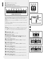
LINE A1 and LINE A
53
a
;
LINE B1 and LINE B2
53
b
.
The total power of all connected loudspeakers of a
single channel shall not exceed 250 W.
Connect the positive wire of the loudspeaker line to
the ‘+’ contact to one of the two amplifier outputs
(either LINE A1 or LINE A2)
53
and the negative
wire to the respective ‘–’ contact.
70/
100 v
0
70/
100 v
0
70/
100 v
0
70/
100 v
0
70/
100 v
0
70/
100 v
0
– + – +
LINE A1
LINE A2
MX 9502 – LOUDSPEAKER RING LINE
('RING MODE')
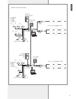
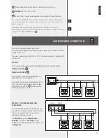
In the (only) MX 9502 model, the loudspeaker line
can wired as a loop (by using both channel outputs),
to ensure continuity of service even in case of
interruption of the line in a point.
The
SET RING
parameter (
DISABL-SURV
>
CALIBRAT
> amplifier >
SET RING
) of every
amplifier with looped loudspeaker lines shall be set to
'
A Ring B Out
'.
Содержание MX 9502
Страница 2: ......

