4
Chapter
47
Remote Management
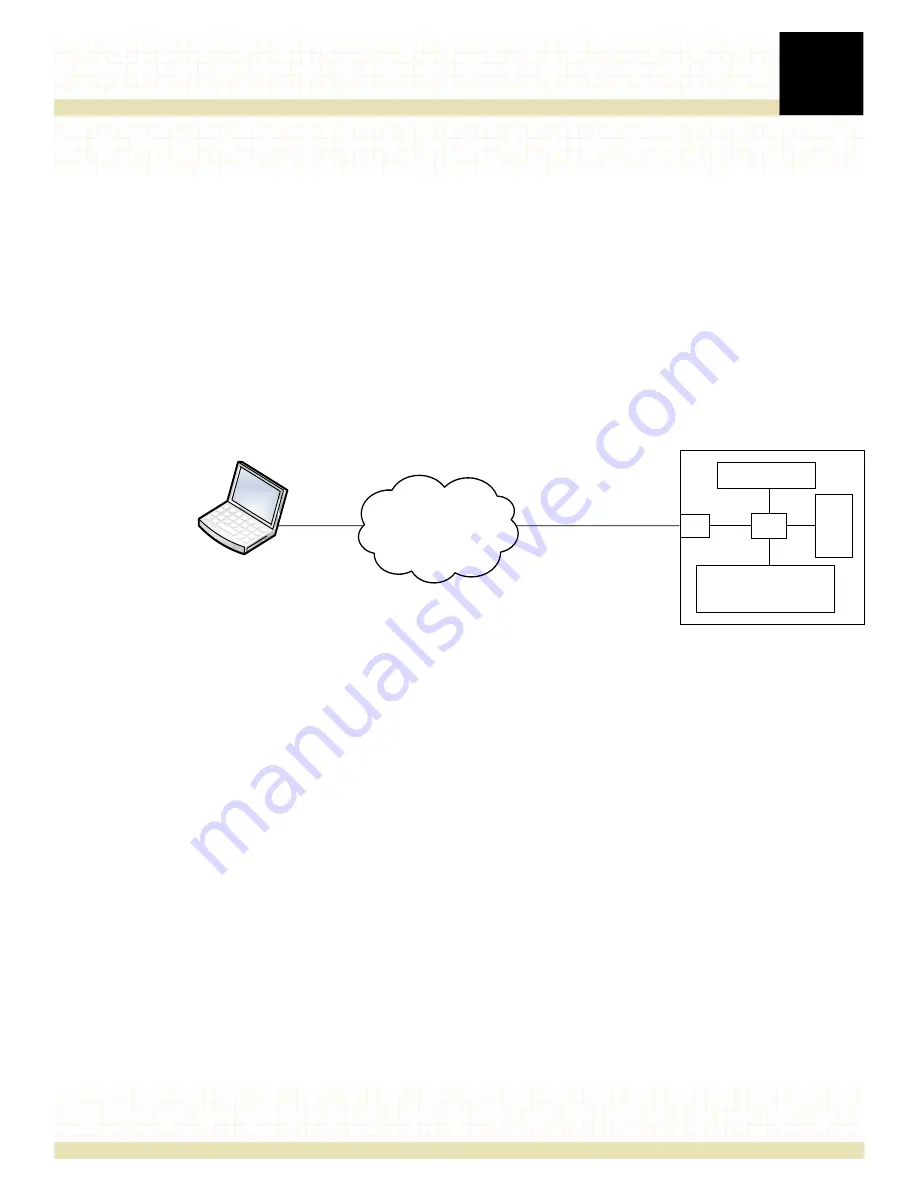
The R220 Network Appliance contains a Baseboard Management Controller (BMC) with
American Megatrends (AMI) MegaRAC® SP-X service processor firmware, which enables
remote management of the R220 Network Appliance via LAN connection.
The MegaRAC SP-X firmware implements IPMI 2.0 and KVM/IP in the service processor,
performing all BMC management tasks defined by IPMI 2.0. As a service processor, the
MegaRAC SP-X firmware provides video redirection and remote monitoring using KVM over
LAN or Serial over LAN (SOL). The MegaRAC SP-X firmware has an embedded Web server and
command line interface that complies with the DMTF SMASH specification and WS-MAN.
Secure-Shell (SSH) based SOL is also available for remote access.
Figure 31. Remote Management of the R220 Network Appliance
The MegaRAC SP-X has a graphical user interface (GUI) that is commonly referred to as the
MegaRAC GUI. It uses standard Internet browsers to simplify these management tasks:
•
monitor the status of sensors, event logs and server health information
•
configure the SMTP and SNMP settings
•
control the server’s operating system
•
perform maintenance tasks, including updating the firmware, restoring the BMC firmware
to default settings, and updating the BIOS
For further information about the AMI MegaRAC SP-X menus and options, please download
the
AMI MegaRAC SP-X User’s Guide
.
Alternatively, you can use IPMI commands in utilities such as
ipmitool
or
ipmiutil
to access and
retrieve management data in the R220. For further information regarding the use of IPMI
commands, please download the
IPMI Second Generation Specification
.
Remote Management
Console*
LAN/SOL
192.168.0.250
255.255.255.0
* Accessing MegaRAC via browser or using IPMI
ĐŽŵŵĂŶĚƐŝŶŶĞƚǁŽƌŬŵĂŶĂŐĞŵĞŶƚƐŽŌǁĂƌĞ
R220 Network Appliance
BMC
System Interface
Monitoring &
Remote Control
SDR
SEL
FRU
NIC
Содержание R220
Страница 1: ...R220 NETWORK APPLIANCE July 2014 Setup Guide ...
Страница 32: ...3 Installing optional components 32 Figure 18 Installing removing the I O module ...
Страница 34: ...3 Installing optional components 34 Figure 20 Inserting the drive carrier into the drive cage ...
Страница 42: ...3 Installing optional components 42 Figure 27 Installing the rail kits into a threaded hole EIA 4 post rack ...
Страница 45: ...3 Installing optional components 45 Figure 29 Installing the rail kits into a Telecom 2 post rack ...


