Chapter 3 - Setup and Installation
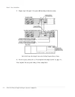
Multi-Port Mirrored Single Host-Single Connection Configuration
83
10
Re-install the Disk I/O card. Repeat step 8 for the second Disk I/O card.
11
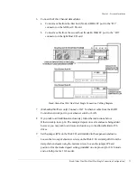
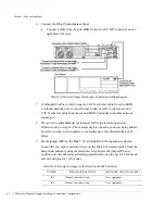
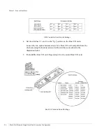
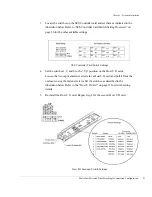
Set the SES Controller Card switches in the daisy-chain enclosure. Refer to the
illustration below. See “SES Controller Card Switch Setting Overview” on page 56 for
additional enclosure settings.
SES Controller Card Switch Settings (Daisy Chain Enclosure)
12
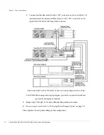
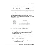
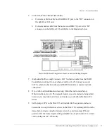
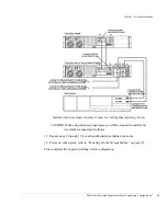
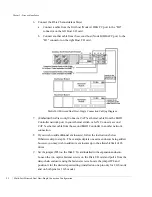
Cable the daisy-chain enclosure to the primary RAID enclosure.
a
Connect a data cable from the “D2” connector on the upper Disk I/O card
installed in the primary RAID enclosure to the “D1” connector on the upper
Disk I/O card installed in the daisy-chain enclosure. Refer to the cabling
illustration on the following page.
b
Connect another data cable from the “D2” connector on the lower Disk I/O
card installed in the primary RAID enclosure to the “D1” connector on the
upper Disk I/O card in the daisy-chain enclosure.
Refer to the illustration on the following page.
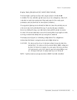
CAUTION:
When using dual loop topologies, you will be required to install and
use volume management software.
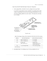
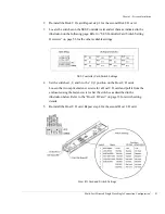
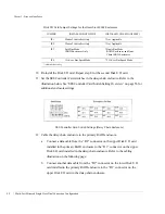
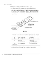
JP3
Split Bus Mode
JBOD Enclosures Only
* Single Bus Mode
RAID Enclosures and Daisy
Chain JBOD Enclosures
JP4
1 Gb/sec Bus Speed Mode
* 2 Gb/sec Bus Speed Mode
* indicates default setting
Disk I/O Card Jumper Settings for the OmniStor 4000F Enclosures
JUMPER
INSTALLED BOTH PINS
INSTALLED ONE PIN (OFFSET)
Содержание OmniStor 4900F Series
Страница 1: ......
Страница 2: ......
Страница 4: ......
Страница 38: ...Chapter 1 Getting Started Audible Alarm 24...
Страница 58: ...Chapter 2 Topologies and Operating Modes Application of Availability 44...
Страница 128: ...Chapter 3 Setup and Installation Powering Off the Storage System 114...
Страница 156: ...Chapter 5 Troubleshooting Problems During Bootup 142...
Страница 178: ...Chapter 6 Maintenance Replacing the Enclosure 164...
Страница 182: ...Appendix A Technical Information Specifications 168...
Страница 196: ...Index 182...

