


Chapter 3 - Setup and Installation
Operating Mode Configuration and Cabling
56
Operating Mode Configuration and Cabling
In this section we provide an overview for the SES Controller card switches and Host
I/O card switches. Following this overview, you will find the detailed instructions to
setup and cable the specific operating mode topology.
SES Controller Card Switch Setting Overview
A word about Fibre Channel device IDs. Under the FC protocol, device IDs can be
generated in several ways: hard addressing, previous addressing, and negotiated
addressing. RAID controllers prefer hard device addressing which ensures that the
device ID will always be the same. The previous addressing method allows the system
to determine whether or not the device has had a previous address ID assigned to it
and will attempt to use that ID (if it is not available it will assign a new ID).
Negotiated addressing occurs when a hard address or a previous address does not exist
and it will then negotiate the bus for a new device ID. The disadvantage of negotiated
device IDs is that there is a potential liability of the device ID changing due to
reconfiguration and therefore could cause potential problems for the RAID
controller’s array drive members.
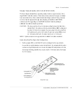
The SES Controller card has a set of switches which configures the enclosure base
address and assigns a device ID to the drive slots, and sets the drive spin-up options.
The disk drive slot IDs are determined by the first three switches, labeled AD0, AD1,
and AD2. They establish a base enclosure hard address and assign the drive slots, each
with a pre-determined set of IDs.
Switches 4, 5 and 6 are spares, and switches 7 and 8 determine the drive spin-up
options.
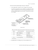
The table on the following page displays the available device ID ranges for each series
of switch settings. Following the diagram, is an illustration which depicts the drive
slot layout within the enclosure.
Содержание OmniStor 4900F Series
Страница 1: ......
Страница 2: ......
Страница 4: ......
Страница 38: ...Chapter 1 Getting Started Audible Alarm 24...
Страница 58: ...Chapter 2 Topologies and Operating Modes Application of Availability 44...
Страница 128: ...Chapter 3 Setup and Installation Powering Off the Storage System 114...
Страница 156: ...Chapter 5 Troubleshooting Problems During Bootup 142...
Страница 178: ...Chapter 6 Maintenance Replacing the Enclosure 164...
Страница 182: ...Appendix A Technical Information Specifications 168...
Страница 196: ...Index 182...


