background image

Chapter 5 Service Commands
Initializing Nonvolatile Information

82

ATL P1000 Series User’s Guide

To execute a nonvolatile memory command:

Procedure

1

On the Service screen, press the appropriate command button 
(Initialize Nonvol Statistics or Initialize Nonvol Config).

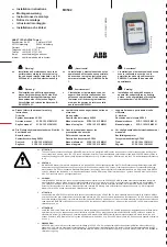
The GUI displays a confirmation screen (see figure 52).

Figure 52  Confirmation 
Screen

2

Press Continue to execute the command.

To cancel the command, press the Cancel button.

Report

System
Off-line

Standby

Load Port

Load Pack

Back

Forward

Home

S

Test

Misc.

Initialize
Nonvol
Statistics

Initialize
Nonvol
Config

Change
Password

Stop

Continue

Cancel

This will reset the library configuration. Continue?

Cancel or Continue

Service

Operator

Tapes

ATL

P R O D U C T S

Содержание P1000 Series

Страница 1: ...ATL P1000 Series Tape Library User s Guide 6221101 03 Ver 3 Rel 0...

Страница 2: ...interference to radio communications Any changes or modifications made to this equipment may void the user s authority to operate this equipment Operation of this equipment in a residential area may...

Страница 3: ...t Minimum 10 A 125 V BATTERY STATEMENT Caution The Dallas Semiconductor DS1230AB 200 component on the robotic controller board inside this product contains a lithium battery Lithium is a hazardous mat...

Страница 4: ...i Forsiktig Kassettbiblioteket inneholder et litiumbatteri Enheten Dallas Semiconductor DS1230AB 200 p robotkontrollkortet inneholder et litiumbatteri Litium kan anses som et farlig materiale Batterie...

Страница 5: ...15 Overhead Clearance 15 Power and Grounding 15 Environmental Requirements 16 Unpacking the P1000 17 Unloading Space Requirements 17 Uncrating the Library 18 Checking the Contents 20 Installing the Sl...

Страница 6: ...y On line 51 Placing the Library Off line 52 Turning Off the Library 52 Inserting Tape Cartridges 52 Opening the Library Doors 54 Manually Ejecting a Cartridge 55 Chapter 4 Operator Commands 57 Access...

Страница 7: ...92 Appendix A Specifications 93 Appendix B Installing the Slide Assembly in the Rack 97 Verifying the Rack Requirements 98 Rack Current Rating Consideration 98 Grounding 98 Temperature 98 Determining...

Страница 8: ...Contents viii ATL P1000 Series User s Guide...

Страница 9: ...ting the Stand alone Library 19 Figure 14 Uncrating the Rack mount Library 20 Figure 15 Removing the Foam Supports Stand alone Library 22 Figure 16 Removing the Stand alone Library from the Pallet 22...

Страница 10: ...en 63 Figure 42 Control Move Cartridge Screen 64 Figure 43 Calibrate Library Screen 67 Figure 44 Control Unload Drive Screen 70 Figure 45 Enter Password Screen 74 Figure 46 Service Screen 75 Figure 47...

Страница 11: ...Table 5 Horizontal Bar Buttons 44 Table 6 GUI Screens 45 Table 7 GUI Security Levels 49 Table 8 Available Settings Configure Options Screen 62 Table 9 Start up Problems 86 Table 10 GUI Problems 87 Ta...

Страница 12: ...Tables xii ATL P1000 Series User s Guide...

Страница 13: ...3 Basic Operations introduces the P1000 s touch screen graphical user interface GUI and explains how to obtain library status change the GUI security level and perform several manual operations such a...

Страница 14: ...described Left side of the library Refers to the left side as you face the component being described Related Documents 0 This section lists documents related to the ATL P1000 library ATL P1000 Documen...

Страница 15: ...L Products Corporate Headquarters 0 To order documentation for the ATL P1000 contact ATL Products Inc 101 Innovation Drive Irvine CA 92612 949 856 7800 800 284 5101 Note When placing an order for a do...

Страница 16: ...Preface xvi ATL P1000 Series User s Guide...

Страница 17: ...rtridges at 35 GB each up to 70 GB compressed The P1000 library is shipped in either a stand alone see figure 1 or rack mount configuration see figure 2 The stand alone P1000 is set on casters The rac...

Страница 18: ...Chapter 1 Library Description 2 ATL P1000 Series User s Guide Figure 2 P1000 Front View Rack mount Library Key lock Bulk pack door Power switch GUI Load port Load pack door Rack not included...

Страница 19: ...the low density library single ended or differential SCSI communication module optical or copper based Fibre Channel communication module The P1000 can be supplied with or upgraded to various Fibre C...

Страница 20: ...ary Description Configuration Options 4 ATL P1000 Series User s Guide Figure 3 P1000 Library Back View Host port DIAG port and library printed circuit boards Tape drive SCSI connectors Bus connector P...

Страница 21: ...ins 9 to 12 in high density configuration only one pack fixed storage array bin 13 in high density configuration only bulk pack bins 14 to 21 load pack bins 22 to 29 Note In the low density configurat...

Страница 22: ...n 23 Bin 24 Bin 25 Bin 26 Bin 27 Bin 28 Bin 29 Bulk pack Load pack1 Bin 3 Bin 4 Bin 5 Bin 0 Bin 1 Bin 2 Bin 6 Bin 7 Bin 8 Drive 0 Drive 2 Drive 1 Drive 3 Nine pack array3 Tape drives2 1 When configure...

Страница 23: ...ridge from a bin or drive The gripper includes bar code scanners which can read standard six character 3 of 9 bar code labels These scanners are used to maintain an inventory of the tape cartridges wi...

Страница 24: ...he following sections describe each of these components Front Panel 1 The front panel consists of the GUI the front doors and key lock the power switch and the load port see figure 5 Figure 5 P1000 Fr...

Страница 25: ...y area changes For further information about the GUI see chapters 3 and 4 Front Doors 1 The front doors provide access to the load packs and the tape drives They allow you to insert and remove tape ca...

Страница 26: ...y for load pack removal Always press the Load Pack button before opening the front door to access the load pack 4 Open the left door and then open the right door Load Port 1 The load port enables you...

Страница 27: ...ts RS 232C diagnostic DIAG port power connector drive access hot swap air filters These components provide the P1000 with power and communication links to external systems Figure 8 Back Panel Stand al...

Страница 28: ...le Components 12 ATL P1000 Series User s Guide Tape Drives 1 The P1000 holds up to four tape drives When fewer than four tape drives are installed the tape drives must occupy consecutive drive bays be...

Страница 29: ...stand alone and rack mount configurations of the P1000 library Installation consists of the following tasks verifying that the installation site meets the site requirements unpacking and positioning...

Страница 30: ...consider the following requirements floor space floor clearance overhead clearance floor strength and inclination power and grounding environmental factors Floor Space 2 Figure 9 shows the floor spac...

Страница 31: ...lly loaded P1000 on the floor or in a rack The floor at the installation site must be level to within 0 25 in 6 4 mm over a 6 ft by 6 ft 1 8 m by 1 8 m area Overhead Clearance 2 To remove the P1000 en...

Страница 32: ...installed in a typical 15A 120V rack If other equipment is installed in the rack determine the total current rating of all the equipment before adding the P1000 library to the rack Grounding 2 The P1...

Страница 33: ...checking the contents of the shipping carton and accessories tray installing the slide assembly in the rack rack mount library only removing the library from the pallet removing the internal packing...

Страница 34: ...shipping materials while uncrating the library Save all packaging materials for possible future shipment of the library Procedure 1 Open the top of the shipping carton by carefully cutting the packag...

Страница 35: ...s Guide 19 Procedure continued 2 Remove these items from the carton and set them aside 3 Remove all foam supports from inside the carton see figure 13 on page 19 and figure 14 on page 20 Figure 13 Unc...

Страница 36: ...To release a clip pinch the center tabs of the clip firmly together and pull on the tabs 5 Lift the carton off of the pallet and set it aside Checking the Contents 2 Compare the contents of the shippi...

Страница 37: ...ee the following section Removing a Stand alone Library from the Pallet To remove a rack mount library from the pallet see Removing a Rack mount Library from the Pallet on page 23 Warning Two people s...

Страница 38: ...3 Attach the ramp to the pallet using fastener strips see figure 16 4 Make any necessary preparations for moving the library This may involve clearing a path to the installation site unlocking doors...

Страница 39: ...ng the instructions in appendix B To remove a rack mount library from the pallet Procedure 1 Remove the plastic bag enclosing the library a Cut along the front seam of the plastic bag b Continue to cu...

Страница 40: ...cking the P1000 24 ATL P1000 Series User s Guide Figure 17 Lifting the Rack mount Library from the Pallet Procedure continued 4 Place the library on the fully extended slide assembly tray see figure 1...

Страница 41: ...e 18 6 Verify that when the slide assembly is fully extended there is adequate clearance around the library to access the back panel and remove the library enclosure 7 Press on the inner channel locks...

Страница 42: ...26 ATL P1000 Series User s Guide Figure 19 Locking the Slide Tray in the Rack Procedure continued 9 Save the shipping carton bag foam supports and pallet for future use These items are required to pac...

Страница 43: ...aution Take precautions to prevent electrostatic discharge whenever you remove the library enclosure or open the library doors Opening the Doors 2 To open the library doors Procedure 1 Locate the key...

Страница 44: ...for the load and bulk packs To remove the shipping restraint Procedure 1 Grasp the front edge of the shipping restraint and carefully push inward at both corners while lifting it up at an angle see fi...

Страница 45: ...d remove the foam block beneath it 4 Lower the extension axis assembly to its normal position on the floor of the library Note Retain the original shipping container and shipping bag pallet ramp acces...

Страница 46: ...2 Attaching a bar code label to each tape cartridge enables the library to identify tape cartridges quickly which speeds the inventory process Bar code labels must conform to the specifications listed...

Страница 47: ...23 Figure 23 Inserting a Bar Code Label Message length 6 00 6 00 6 00 Traditional tests PASS PASS PASS Bar growth IN TOL IN TOL IN TOL PCS OK OK OK Print quality grade B C C Formatting checks PASS PA...

Страница 48: ...ridge or existing data to be modified or erased To write enable a cartridge move the write protect switch to the right see figure 24 The orange tab disappears Figure 24 Setting the Write protect Switc...

Страница 49: ...of the nine storage bins above the tape drives See figure 25 for the correct tape cartridge orientation Each cartridge should slide into place with very little force If a cartridge does not slide into...

Страница 50: ...rtridge snaps into place If a cartridge does not snap into place check for correct orientation and structural integrity 2 Verify that each cartridge is properly oriented and seated in the bin see figu...

Страница 51: ...elines 2 When connecting the host computer s to the library follow these guidelines Connect each host to a SCSI connector on the back panel of the library When more than one device is on a SCSI bus da...

Страница 52: ...ected to the host connector on the rear panel of the library Since there is only one SCSI bus use all of the SCSI cables from the accessories kit to daisy chain the library to each of the tape drives...

Страница 53: ...nnected to tape drive 3 and daisy chained to tape drive 2 lower drives The first SCSI bus is terminated at drive 0 the second is terminated at drive 2 For this configuration you need the following ite...

Страница 54: ...Host Computers 38 ATL P1000 Series User s Guide In the five host configuration see figure 28 five hosts are connected to the library requiring five SCSI terminators Figure 28 Five Host SCSI Configurat...

Страница 55: ...rn on the library Procedure 1 Verify that all internal packaging is removed the front doors and load port are closed the library enclosure is installed all back panel connections are secure 2 At the f...

Страница 56: ...st the library see chapter 5 Note You must have either Operator or Service access privileges to access the options described in chapter 4 and Service access privileges to access the options described...

Страница 57: ...l user interface GUI GUI components GUI screens obtaining library status changing the GUI security level performing manual operations turning the library on and off placing the library on or off line...

Страница 58: ...ter and in chapters 4 and 5 require an understanding of the GUI screens GUI Components 3 The GUI screen consists of the following components a vertical bar at the left side of the screen a horizontal...

Страница 59: ...n line and standby status Load Port button Pressing the Load Port button causes the load port to open allowing you to insert or remove a tape cartridge Load Pack button Pressing the Load Pack button p...

Страница 60: ...you backward screen by screen through previously selected screens Forward button Pressing this button moves you forward screen by screen through previously selected screens Home button Pressing this...

Страница 61: ...reen you must have Operator or Service access privileges Service This screen contains reporting functions system tests and miscellaneous commands To use this screen you must have Service access privil...

Страница 62: ...iew screen is divided into three sections see figure 32 Drives Activity Load Pack Figure 32 Overview Screen System Off line Standby Load Port Load Pack Overview Tapes Operator Back Forward Home U Driv...

Страница 63: ...section This opens a Tape Drive Status box see figure 33 Use the arrow buttons to scroll through the list of drives To return to the Overview screen press the Tape Drive Status box Figure 33 Overview...

Страница 64: ...lement contains a cartridge look at the appropriate section of the screen For example to determine whether there is a cartridge in the gripper look at the Transport section of the screen The Storage a...

Страница 65: ...r level after executing an Operator or Service level command Security Level Indicator Description Service S This security level provides access to all GUI screens Overview Tapes Operator and Service a...

Страница 66: ...enter a password A password is required to enter a security level higher than the one currently set The default passwords are Service 5678 Operator 1234 User 2222 Import Only 1111 4 Press the Select b...

Страница 67: ...the library Procedure 1 Verify that all internal packaging is removed the front doors and load port are closed the library enclosure is installed all back panel connections are secure 2 At the front...

Страница 68: ...line The library completes the current command and then stops 2 Verify that the GUI displays System Off line 3 Verify that the gripper is empty by checking the Overview screen 4 If there is a tape car...

Страница 69: ...The library unlocks the load port and the load port door springs open slightly Warning Mechanical hazards may be exposed when the load port is partially open or closed Do not attempt to insert your ha...

Страница 70: ...load and bulk packs or to load the library with tape cartridges To open the library doors Procedure 1 If the door is locked unlock it 2 Press the Load Pack button on the left side of the GUI The libra...

Страница 71: ...s Unload the tape cartridge rewinds Depending on the tape cartridge position this may take from 10 to 120 seconds When the rewind process is complete the Operate Handle indicator lights 4 When the Ope...

Страница 72: ...Chapter 3 Basic Operations Performing Manual Operations 56 ATL P1000 Series User s Guide...

Страница 73: ...ary options move a tape cartridge inventory the tape cartridges calibrate the library exercise the library unload a tape drive unload the load port The Operator screen is restricted to persons with Op...

Страница 74: ...screen see figure 37 Figure 37 Enter Password Screen 2 Enter the Operator or Service password Note The default Operator password is 1234 To change the Operator password see Changing Passwords on page...

Страница 75: ...valid the GUI displays the Operator screen see figure 38 Figure 38 Operator Screen Control System Off line Standby Load Port Load Pack Overview Tapes Operator Back Forward Home O Config Configure Lib...

Страница 76: ...ation Procedure 1 On the Operator screen press the Configure Library button The GUI displays the Configure Library screen see figure 39 Figure 39 Configure Library Screen 2 Press the Configure button...

Страница 77: ...CSI devices include the library robotics the host computer the library tape drives and internal and external hard disk drives b Press the arrow buttons to scroll through the available settings for tha...

Страница 78: ...option is enabled the library performs an inventory automatically upon power up Barcode Labels Enable Disable When this option is enabled the library scans bar codes during inventory Disable this opt...

Страница 79: ...buttons scroll through the available option settings 4 When the desired setting appears in the New Value field press the Execute button The new value is added to the library configuration 5 Repeat st...

Страница 80: ...repare the cartridge by issuing an Unload Drive command see Unloading a Drive on page 70 To move a cartridge Procedure 1 On the Operator screen press the Move Cartridges button The GUI displays the Co...

Страница 81: ...rce information and the Destination box becomes active 3 Identify the destination element a Press the appropriate element button Storage Bin Tape Drive Load Port or Gripper The GUI displays a range of...

Страница 82: ...fixed storage bins load pack bins and the load port Library elements containing unlabeled cartridges are marked full with no label To perform an inventory press the Inventory Tapes button on the Oper...

Страница 83: ...brate the library Procedure 1 On the Operator screen press the Calibrate Library button The GUI displays the Calibrate Library screen see figure 43 Figure 43 Calibrate Library Screen 2 Press the butto...

Страница 84: ...ATL P1000 Series User s Guide The GUI displays a Command In Progress screen during the calibration process To cancel the calibration process press the Abort button 3 When the calibration is complete...

Страница 85: ...mand tests the robotics and the calibration by moving cartridges randomly from one storage location to another To exercise the library press the Exercise Library button on the Operator screen The GUI...

Страница 86: ...cedure 1 On the Operator screen press the Drive Unload button The GUI displays the Control Unload Drive screen see figure 44 Figure 44 Control Unload Drive Screen 2 Use the arrow buttons to highlight...

Страница 87: ...Auto Load option is disabled see Configuring Library Options on page 62 Note You can also use the Move Cartridges command to unload the load port see Moving a Cartridge on page 64 This command is esp...

Страница 88: ...Chapter 4 Operator Commands Unloading the Load Port 72 ATL P1000 Series User s Guide...

Страница 89: ...ouch screen graphical user interface GUI Using this screen you can generate reports test the library initialize nonvolatile information change passwords The Service screen is restricted to persons wit...

Страница 90: ...b The GUI displays the Enter Password screen see figure 45 Figure 45 Enter Password Screen 3 Enter the Service password Note The default Service password is 5678 To change the Service password see Cha...

Страница 91: ...ys the Service screen see figure 46 Figure 46 Service Screen Report System Off line Standby Load Port Load Pack Back Forward Home S Test Misc Statistics SysTest Library Results Actuator Auto Clean Sys...

Страница 92: ...t side of the screen to scroll through the report page by page When you are finished viewing the report press the Back button to return to the Service screen Figure 47 shows a sample statistics report...

Страница 93: ...52 Vertical Position in 3 126 Extension Position in 0 015 Gripper Position Closed Rotary Position Front System Off line Standby Load Port Load Pack Stop ATL P R O D U C T S Service Tapes Operator Back...

Страница 94: ...re 50 Report AutoClean Status Screen Back Forward Home S Report AutoClean Status Auto Clean Enabled FALSE Auto Clean State Idle Cleaning Operation Count 0 Bad Operation Count 0 Untracked Operation Cou...

Страница 95: ...On the Service screen press the SysTest Library button The GUI displays the Test SysTest Library screen see figure 51 Figure 51 Test SysTest Library Screen 2 Select one of the following system test op...

Страница 96: ...est options press the Execute button The GUI displays a Command In Progress screen To cancel the system test press the Abort button Note If you selected the Continuous option in step 3 you must press...

Страница 97: ...eplacing the robotic controller card The Service screen provides two commands involving information stored in nonvolatile memory Initialize Nonvol Statistics This command purges nonvolatile memory of...

Страница 98: ...onfig The GUI displays a confirmation screen see figure 52 Figure 52 Confirmation Screen 2 Press Continue to execute the command To cancel the command press the Cancel button Report System Off line St...

Страница 99: ...splays the Service Change Password screen see figure 53 Figure 53 Service Change Password Screen 2 Press the button that corresponds to the security level password you wish to change 3 Enter a new pas...

Страница 100: ...nds Changing Passwords 84 ATL P1000 Series User s Guide Procedure continued 5 Reenter the new password Asterisks representing each character appear in the Reenter box 6 Press the Execute button The ne...

Страница 101: ...s Several of these problems produce error messages on the touch screen graphical user interface GUI called sense data values Sense data value messages consist of a number and a description of the erro...

Страница 102: ...itialization Determine the failure type by checking any previous error codes returned to the host computer Correct the cause of the error One or more tape drives fail to spin up during start up Check...

Страница 103: ...ed on and the library is connected to a grounded electrical outlet Contact an authorized field service engineer The GUI does not respond when pressed Contact an authorized field service engineer An er...

Страница 104: ...sed The gripper partially grips a tape cartridge Issue a Move Cartridge command to move the cartridge from the gripper to an empty storage element The bar code reader on the gripper fails 1 Verify tha...

Страница 105: ...or A cartridge is in the gripper at start up when a move command is requested or after a place command is executed 1 Open the doors safely a Press the Load Pack button b Open the left door c Open the...

Страница 106: ...If the host and the library are still not communicating contact an authorized field service engineer A cable or terminator is disconnected from the library back panel Reconnect the cable or terminato...

Страница 107: ...ree of obstruction 3 Verify that the library is on line and the Stop button is released 4 Retry the command A flash memory error is reported Contact an authorized field service engineer A maximum temp...

Страница 108: ...e library is unable to communicate with a drive This is indicated by a Drive Communication Time out error Contact an authorized field service engineer The tape drive does not eject a cartridge 1 Reset...

Страница 109: ...ics Unit Dimensions Width 17 3 in 44 cm Depth 28 5 in 72 cm Footprint 3 4 ft2 0 32 m2 Height 19 8 in 50 cm Unit Weight Rack mount model 89 lb 40 kg without cartridges Stand alone model 101 lb 46 kg wi...

Страница 110: ...n 52 F 11 C per hour Temperature shipping and storage Dry bulb 40 F to 151 F 40 C to 66 C Wet bulb 115 F 46 C maximum Thermal transition 54 F 30 C per hour Relative humidity Operating 20 to 80 non con...

Страница 111: ...Appendix A Specifications ATL P1000 Series User s Guide 95 Acoustical Noise Sound power level Operating 6 0 Bel Idle 5 0 Bel Sound pressure bystander Operating 49 dB...

Страница 112: ...Appendix A Specifications 96 ATL P1000 Series User s Guide...

Страница 113: ...adjusting the slide assembly to allow for required clearances Warning Use safe lifting practices when moving the slide assembly or the library The slide assembly weighs about 25 lbs 11 25 kg and its s...

Страница 114: ...f the rack before installing more than one P1000 library The P1000 library is rated 6A 3A 120V 230V This means that no more than two libraries can be installed in a typical 15A 120V rack If other equi...

Страница 115: ...tioning the Slide Assembly As indicated in figure 54 the bottom edge of each slide assembly bracket must line up with the end of a rack unit 2 If the rack retma rail holes are not threaded attach the...

Страница 116: ...support screw into each retma rail just below the desired position of the slide assembly bracket Use any long screws that fit into the retma rail holes 4 Make sure the support screws are level with o...

Страница 117: ...ift the slide assembly and tilt it sideways b Insert the back end of the slide assembly into the front of the rack keeping the slide assembly above the temporary support screws c When the rear bracket...

Страница 118: ...talling the Slide Assembly in the Rack 102 ATL P1000 Series User s Guide Figure 55 Installing the Slide Assembly in the Rack Slide assembly Support screw Mounting screws Mounting screws Support screw...

Страница 119: ...ds at least 30 in 76 2 cm from the front of the rack If the slide assembly and rack do not meet the above requirements complete the procedures in this section to adjust the slide assembly The number o...

Страница 120: ...ge 105 The intermediate channels are secured by the intermediate channel locks which are located on the inner back edge of the intermediate channels d Release the intermediate channel locks by rotatin...

Страница 121: ...Tray on the Slide Rails B To adjust the slide assembly tray on the slide rails Procedure 1 Loosen the inner nuts on both sides of the slide assembly see figure 58 on page 106 Access these nuts from u...

Страница 122: ...the nut with an 11 32 inch open ended wrench and then tightening its corresponding screw with a Phillips screwdriver c Press on the inner channel locks to release them see figure 57 on page 105 d Pus...

Страница 123: ...the Slide Assembly ATL P1000 Series User s Guide 107 Now that the slide assembly is properly installed and adjusted you are ready to remove the P1000 from the shipping pallet and mount it in the rack...

Страница 124: ...Appendix B Installing the Slide Assembly in the Rack Adjusting the Slide Assembly 108 ATL P1000 Series User s Guide...

Страница 125: ...ary operation E extension axis assembly Mounted on the vertical axis the extension axis assembly consists of the gripper assembly and the horizontal axis on which the gripper assembly is mounted exten...

Страница 126: ...y that allows you to insert or remove a single cartridge M MSBF Mean swaps between failures MTBF Mean time between failures MTTR Mean time to repair N NVRAM Nonvolatile random access memory RAM O on l...

Страница 127: ...s data from and to a tape cartridge U UL Underwriters Laboratories V vertical belt The drive belt connecting the vertical motor to the vertical axis assembly vertical carriage assembly The crossbar an...

Страница 128: ...Glossary 112 ATL P1000 Series User s Guide...

Страница 129: ...y 1 Change Password command 83 configuration options 3 configurations library 1 6 rack mount 1 2 stand alone 1 Configure Library command 60 Configure Options command 62 Configure Library screen 60 Con...

Страница 130: ...rizontal actuator 7 host computers connecting 35 humidity 16 I Import Only password 50 security level 49 Initialize Nonvol Config command 81 Initialize Nonvol Statistics command 81 inserting tape cart...

Страница 131: ...k mount configuration 1 2 receiving the library 17 removing load and bulk packs 27 shipping restraint 28 Report Actuator Status screen 77 Report AutoClean Status screen 78 Report Statistics screen 76...

Страница 132: ...nd bulk packs 34 placing in storage bins 32 setting the write protect switch 32 tape drives 12 problems troubleshooting 92 unloading 70 Tapes screen 48 Temp Detection option 62 temperature 16 Test Sys...

Отзывы: