background image

56

57

PICTURE 4-29

REMOTE DEVICE

Filter

None

Delete

Manual Add

IP Search

Add

OK

Cancel

  4 

IP Address 

Port 

Device ID 

Manufacturer  Type

  1 

10.1.1.65 

 Port 1  YZC2OC061966 

Private 

IPC

  2 

10.1.1.67 

Port 2 

YZCAU192012 

Private 

IPC

  3 

10.1.1.68 

Port 4  TC2FW25600095 

Private 

IPC

  4 

196.219.8.50  4000 


Private 

channel  Edit  Delete  Status  IP Address 

Port 

Device ID


196.610.6.46  37777 


10.1.1.67 

Port 2 

YZCAU192012


10.1.1.68 

Port 4 

TC2FW25600095


10.1.1.65 

Port 1 

YZC2OC061966 

Device Added

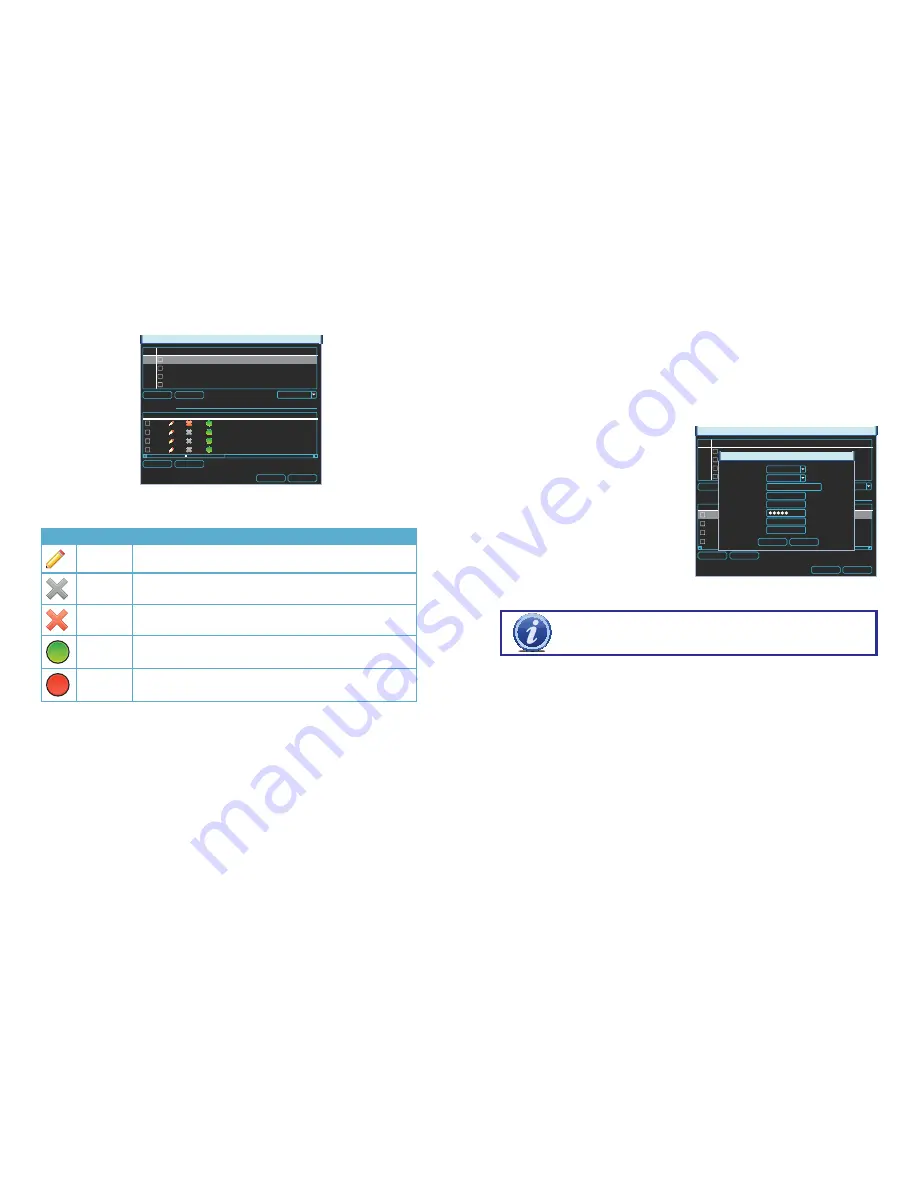
When the window opens, you will be presented with a list of all connected devices in the 
lower portion. This section, marked Device Added, indicates the status of each device along 
with other information about it. 

Icon

Meaning

Description

Editable

You may edit the settings on this device by double-clicking on it

Cannot 
Delete

This device is connected directly to the NVR and must be physically 
unplugged to be removed from this list.

Removable

This device may be deleted from the list by checking the box next to 
it and clicking on the 

Delete

 button below.

Device 
Status OK

The connected device is operating normally.

Device 
Error

There is an issue with the connected device that is preventing it from operating 
normally.

Clicking on 

IP Search

 under the upper portion of the window will generate a list of all devices 

that the NVR was able to locate - both directly connected as well as connected to the same 
network as your system. Items showing a short IP address beginning with “10” are cameras 
directly connected to the NVR and who’s IP addresses were assigned by the NVR itself. Care 
should be taken that you do not attempt to connect a device that is already connected to the 
system as it will create a duplicate video feed and could cause connectivity issues.

EDIT

Double-clicking on a device in the 

Device Added

 portion of the window will display 

information regarding the connected remote device. Making any changes within this window 
will not change anything on the camera or remote device itself. To make those changes, you 
will need to access the camera or other remote device (such as a DVR) directly, or through 
one of the remote methods described in the 

Remote Monitoring Guide

Once you have made those changes, you will need to update the user name and password 
within the 

Edit

 window. Failing to change these in this window will result in an on-screen 

message about incorrect password and may lock you out of the IP camera for a period of 30 
minutes in the case of QC-Series cameras - other brands may vary.

It is important that you do not remove the 
device you are making the changes upon 
from the list of connected devices before 
editing the information in the 

Edit

 window. If 

you later remove the device from the list and 
wish to reconnect, you will need to do so 
using the 

Manual Add

 feature as described 

below.

PICTURE 4-30

REMOTE DEVICE

Filter

None

Delete

Manual Add

IP Search

Add

OK

Cancel

  4 

IP Address 

Port 

Device ID 

Manufacturer  Type

  1 

10.1.1.65 

 Port 1  YZC2OC061966 

Private 

IPC

  2 

10.1.1.67 

Port 2 

YZCAU192012 

Private 

IPC

  3 

10.1.1.68 

Port 4  TC2FW25600095 

Private 

IPC

  4 

196.219.8.50  4000 


Private 

channel  Edit  Delete  Status  IP Address 

Port 

Device ID


196.610.6.46  37777 


10.1.1.67 

Port 2 

YZCAU192012


10.1.1.68 

Port 4 

TC2FW25600095


10.1.1.65 

Port 1 

YZC2OC061966 

Device Added

EDIT

Channel
Manufacturer
IP Address
TCP Port
User
Password
Remote Channel
Decoder Buffer

1
Private
IPC.myq-see.com
32555
admin

1
280

Save

Cancel

IMPORTANT!

  To  avoid  connection  issues,  you  should  not  change  the 

information within the 

Edit

 window unless you have first made those changes 

to the remote device itself. 

ADDING AND DELETING REMOTE DEVICES

The lower portion of the window shows all devices currently connected to your NVR. If all of 
your channels are occupied, you will need to delete one of the connected devices from this 
list by selecting the check box next to it and clicking delete. Items with a gray “

X

” are directly 

connected to your NVR and may only be removed by physically disconnecting them from your 
system. 
Clicking on the 

IP Search

 button will create a list of all remote devices that the NVR was able 

to detect. You may limit this search to only IP cameras by selecting 

IPC

 in the 

Filter

 pull-

down. Items being accessed by your NVR over the Internet will not appear in the list at the top 
of the window. They must be added manually (see below).
If you have an available channel, you may add a device by selecting the check box next 
to it and then clicking 

Add

. Please note that the NVR will connect automatically only with 

devices from compatible manufacturers (see 

Section 2.4 IP Cameras

 or 

Section A.2 

Specifications

 for a list of compatible manufacturers) using their default user names and 

passwords. If these have been changed, you will need to use the 

Manual Add

 feature 

instead.

Содержание QC8016

Страница 1: ...1 H 264 NETWORK VIDEO RECORDERS Variable D1 and HD Recording Options User Manual MODEL QC804 QC808 QC8016...

Страница 2: ...g with free downloadable firmware updates for your NVR Register today at www Q See com Please see the back of this manual for exclusions This manual is written for the Q804 QC808 and QC8016 Network Vi...

Страница 3: ...Zoom 30 Back up 31 3 6 Schedule 32 3 7 Motion Video Loss and Camera Masking Detection 34 Motion Detection 34 Video Loss 35 Camera Masking 35 Event Response 35 3 8 Backup 37 4 MENUS 40 4 1 Main Menu 41...

Страница 4: ...dry To clean the outside case of the NVR gently wipe using a lightly dampened cloth only use water do not use solvents n Do not operate this NVR without the cover securely in place Do not attempt to...

Страница 5: ...d false alarms and avoid unnecessary record triggering Multiple Backup Options A built in USB port gives you the option of backing up and transferring your video footage using a flash drive or externa...

Страница 6: ...Port For use with flash drive when backing up or updating firmware Not for use with mouse Rear Panel Number Item Function 1 POE Power Input 48V power input for the Power Over Ethernet POE block 2 POE...

Страница 7: ...unctions are used is based on the context of where they are used Some examples are LEFT CLICK Selecting an item Opening a menu Checking a box or motion detection status Selecting letters numbers or sy...

Страница 8: ...Begins playback of selected video or pauses current video Adjust Iris light level in PTZ mode 7 Previous Record Goes to previous video in Playback mode Adjust focus when in PTZ mode 8 Reverse Pause R...

Страница 9: ...t it will receive power immediately but there may be a delay of up to a minute before the camera s signal appears on the screen as the system establishes connectivity NVR POE Block POE Block NVR POE B...

Страница 10: ...e functions or options available in a given menu For many users these basic operating instructions may be all they need to operate their security system But because this system offers many more featur...

Страница 11: ...de Right clicking the mouse or pressing the Enter button on the front of the NVR will bring up the Shortcut Menu covered on the next page allowing you to select an action however before you can access...

Страница 12: ...d 3 7 respectively Stop All selected cameras stop recording You can assign the same values to all cameras by selecting the desired status in the All column OK Cancel ALARM OUTPUT ALARM TYPE All 1 2 3...

Страница 13: ...Play video forward or backward 6 Frame Advance Each click advances or reverses the playback by one second 7 Slow Fast Play Speed up or slow down playback Four speeds each 8 Volume Adjust playback vol...

Страница 14: ...ocate dates with video records STEP 2 Click the Event List button to bring up a list of recorded events They will be listed in order of starting time and will have a one letter code after the time to...

Страница 15: ...s will start the playback in the desired direction The button s icon will change to a Pause icon to allow you to freeze the playback as needed If you have Sync unchecked clicking Stop will end the pla...

Страница 16: ...apter where one can back up saved files located across multiple days Instead this procedure allows you to quickly save files or clips that you have located without having to search for them again Once...

Страница 17: ...00 00 00 24 00 00 00 24 00 00 00 24 00 Copy Default OK Cancel MD Alarm MD Alarm 0 3 6 9 12 15 18 21 24 06 24 2012 Jan 2012 Su Mo Tu We Th Fr Sa 1 2 3 4 5 6 7 8 9 10 11 12 13 14 15 16 17 18 19 20 21 2...

Страница 18: ...overlaying that camera s view By default each block of the grid will have a red hue indicating that it is sensitive to motion detection Clicking in a block will make it clear meaning that motion dete...

Страница 19: ...ipient address Record Channel When one camera detects an event you can set the NVR to activate recording on other cameras PTZ Activation When selected this will cause a connected Pan Tilt Zoom camera...

Страница 20: ...2 01 25 12 07 14 16 38249 1 M 01 25 12 23 19 01 01 25 12 23 48 13 56921 1 M 01 27 12 03 04 54 01 27 12 03 07 52 2309 1 M 01 27 12 03 11 43 01 27 12 03 14 27 2217 1 M 01 27 12 08 06 07 01 27 12 08 53 0...

Страница 21: ...here are seven submenus available Search Info Setting Remote Device Advanced Backup and Shutdown Clicking on an icon will take you to that function or the submenu it represents The Search menu is cove...

Страница 22: ...cessor NotePad or other text reader application PICTURE 4 6 PICTURE 4 7 VERSION This display shows system hardware and firmware specifications The hardware data shows the number of channels the system...

Страница 23: ...ty across all channels upon opening You have the option to search by a specific time period and channel by setting the criteria and pressing Search Network Load You can track the traffic load of your...

Страница 24: ...mon to North America Video output can be switched to PAL for areas where that is used Device No If you are controlling more than one NVR with a single remote this allows you to give each NVR a separat...

Страница 25: ...frame rate when the system detects motion or an alarm triggers an event Your selections in the pull down are Regular MD Motion Detection or Alarm Compression The default setting is H 264 which is an...

Страница 26: ...meras are enabled in the Schedule window see Section 3 7 The actual settings for the Snapshot feature are configured in the Snapshot window which can be opened by clicking on the Snapshot button at th...

Страница 27: ...Name You can name each channel up to 25 characters An example is naming the channels based on where they re located Time Display and Channel Display These buttons enable their respective displays on t...

Страница 28: ...ct and display video remote cameras connected to your system must be located and added manually This can be done through the process described in Section 2 4 IP Cameras at the beginning of this manual...

Страница 29: ...nge these in this window will result in an on screen message about incorrect password and may lock you out of the IP camera for a period of 30 minutes in the case of QC Series cameras other brands may...

Страница 30: ...o cameras and DVRs which were previously connected but later removed from the list of connected items Items being accessed from outside your local network will also need to be added using this button...

Страница 31: ...User button Administrator Users have control over 60 different functions while basic Users have 35 functions that can be allowed or denied PICTURE 4 35 A user or group name can consist of at most eigh...

Страница 32: ...etal You must push in the orange tab above the port with a small item like the end of a paperclip while inserting the wire lead When the wire is sufficiently inserted release the orange tab Pull gentl...

Страница 33: ...ain Menu STEP 3 Click the save button once you have entered the settings If you are operating an identical PTZ camera on another channel you may use the Copy and Paste buttons to apply those settings...

Страница 34: ...nction In addition there are other functions that can be engaged in this window AutoPan This will cause the camera to automatically rotate Flip Most PTZ cameras have a mechanical stop which will preve...

Страница 35: ...alarm input a relay should be used to separate them Parameter Grounding Alarm Ground line Alarm Input 1 2 8 becomes valid in low voltage 1 NO C 2 NO C Two NO activation outputs CTRL 12V Controls the...

Страница 36: ...larm device To avoid overloading please read the following relay parameters sheet carefully RS485 A B cable is for the A B cable of the PTZ camera 6 3 ALARM SETUP AND ACTIVATION Once external alarms a...

Страница 37: ...seconds before the PTZ camera s activates Setting up these pre programmed functions is covered in Section 5 2 PTZ Control and Setup Tour When enabled this causes the NVR s display to cycle through se...

Страница 38: ...ts Whether installing the drive for the first time or removing the old one to install a new one the steps are largely the same STEP 1 Disconnect the NVR from the power source as well as any other conn...

Страница 39: ...ta cable error d Hard drive malfunction e NVR hardware malfunction APPENDIX 8 There is no audio when monitoring Possible Causes a Channel with audio is not full screen make the channel you want to hea...

Страница 40: ...Record Resolution 1080P 1920 1080 720P 1280 720 D1 704 576 704 480 Record Frame Rate D1 30fps camera 720p 30fps camera 1080p 30fps camera D1 30fps camera 720p 30fps camera 1080p 15fps camera D1 30fps...

Страница 41: ...by improper operation 2 Improper equipment operation environment and conditions e g improper power extreme environmental temperatures humidity lightning and sudden surges of electricity 3 Damage cause...

Страница 42: ...82 Digital Peripheral Solutions Inc 8015 E Crystal Drive Anaheim CA 92807...

Отзывы: