background image

48

49

RECORD SETTING

This window allows you to manage the quality of the recording from each channel as well as 
the transmission rate and whether there’s an accompanying audio feed.

As with other windows described earlier, each 
channel can be set individually or all at the 
same time. Settings can be copied from one 
channel and pasted to another. Your settings 
will only be saved if you exit the window by 
clicking 

OK

. Right-clicking or hitting 

Cancel


will leave the system with your previous 
settings.
There are settings both for the Main Stream 
- the video files that record directly onto the 
NVR’s hard drive, and the Extra Stream which 
is the signal accessed by mobile and remote 
devices. These streams run in parallel with 
the main stream sent to the hard drive and 
they do not affect each other.
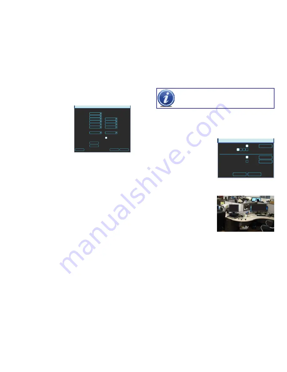
RECORD SETTING

Main Stream

Extra Stream

Channel
Type
Compression
Resolution
Frame Rate (FPS)
Bit Rate Type

Bit Rate (Kb/S)
Reference Bit Rate   4096-8192Kb/S 


192-1024Kb/S

Audio/Video

1
Regular

1.3M
25
Constant

8192

CIF

H.264

H.264

7
Constant

256

OVERLAY

SNAPSHOT

Copy

OK

Cancel

PICTURE 4-16

NOTE!

 Generally, the trade-off for higher quality and increased frame rate is 

the amount of room a video file will take on the drive along with how much 
“bandwidth”  the  signal  takes  up  within  the  system.  The  larger  the  files,  the 
sooner the hard drive will fill up. Setting the drive to overwrite older files will 
allow you to maximize the capabilities of your system and cameras.

Audio/Video

 – Set by default to enable your system to send both video and audio feeds 

(audio requires a microphone located at or near the camera) to your Extra Stream 
for use by mobile and remote devices. Disabling a channel can be done to prevent 
remote users from accessing a specific camera, but this is better handled in 

Account

 (see 

Section 4.5 Advanced Settings

).

Type

 – You are able to change the recording quality based on the type of recording taking 

place. For instance, you may have the NVR record at a slower frame rate and/or 
resolution during Regular recording to save disk space with the system switching to a 
higher resolution and frame rate when the system detects motion or an alarm triggers 
an event. Your selections in the pull down are; Regular, MD (Motion Detection) or 
Alarm.

Compression

 – The default setting is H.264, which is an industry-standard format that greatly 

reduces the file size of recordings while maintaining the maximum amount of visual 
clarity. It cannot be changed.

Resolution

 – This is generally dependent upon the camera connected to the NVR. When the 

NVR connects to a camera it’ll determine the maximum resolution. You can always 
set this to a lower value. In the Extra Stream, the resolution will be much less - the 
320x240 pixel CIF resolution - to allow the video feeds to be uploaded.

Frame Rate (FPS) 

– Like Resolution, this is dependent upon the camera. It is variable 

between 1 to 30 frames per second. The higher the number, the smoother the 
playback.

Bit Rate Type

 – Variable  versus Constant. Variable provides better compression, but issues 

may arise when streaming for remote viewing.

Bit Rate (KB/S)

 –Also based on the camera that is connected to your system, this is the 

maximum bit rate the selected channel can utilize. You may use the options provided, 
or you may customize the bit rate to best suit your network’s capabilities. Your 
network may not have enough bandwidth to handle maximum rates from all of your 
cameras. Adjusting these settings to suit your network will improve performance and 
on-screen image quality.

OVERLAY

Save

Cancel

Set

Cover-Area

Monitor

Set

Time Display

Monitor

Set

Channel Display

Monitor

1

2 3 4

Overlay

 – This window allows you to 

configure on-screen displays from 
the camera as well as providing 
the ability to mask off areas from 
view.  This latter feature is useful 
in circumstances such as when a 
camera’s field of view includes a 
combination lock or other similar 
situation. The local user will be able 
to view the area but remote viewers 
cannot see the area. These privacy 
blocks affect both the live view and 
playback. 

Cover Area

 - Clicking the 

Monitor

 button will 

reveal four numbered buttons. These 
are the four on-screen areas that you 
can set to cover. 


Click 

Set

 to reveal a live view of 

the camera’s feed. There will be a 
numbered area on the display which 
can be moved and re-sized. You 
can deactivate any of these areas by 
deselecting the numbered button.

PICTURE 4-17

PICTURE 4-18

Содержание QC8016

Страница 1: ...1 H 264 NETWORK VIDEO RECORDERS Variable D1 and HD Recording Options User Manual MODEL QC804 QC808 QC8016...

Страница 2: ...g with free downloadable firmware updates for your NVR Register today at www Q See com Please see the back of this manual for exclusions This manual is written for the Q804 QC808 and QC8016 Network Vi...

Страница 3: ...Zoom 30 Back up 31 3 6 Schedule 32 3 7 Motion Video Loss and Camera Masking Detection 34 Motion Detection 34 Video Loss 35 Camera Masking 35 Event Response 35 3 8 Backup 37 4 MENUS 40 4 1 Main Menu 41...

Страница 4: ...dry To clean the outside case of the NVR gently wipe using a lightly dampened cloth only use water do not use solvents n Do not operate this NVR without the cover securely in place Do not attempt to...

Страница 5: ...d false alarms and avoid unnecessary record triggering Multiple Backup Options A built in USB port gives you the option of backing up and transferring your video footage using a flash drive or externa...

Страница 6: ...Port For use with flash drive when backing up or updating firmware Not for use with mouse Rear Panel Number Item Function 1 POE Power Input 48V power input for the Power Over Ethernet POE block 2 POE...

Страница 7: ...unctions are used is based on the context of where they are used Some examples are LEFT CLICK Selecting an item Opening a menu Checking a box or motion detection status Selecting letters numbers or sy...

Страница 8: ...Begins playback of selected video or pauses current video Adjust Iris light level in PTZ mode 7 Previous Record Goes to previous video in Playback mode Adjust focus when in PTZ mode 8 Reverse Pause R...

Страница 9: ...t it will receive power immediately but there may be a delay of up to a minute before the camera s signal appears on the screen as the system establishes connectivity NVR POE Block POE Block NVR POE B...

Страница 10: ...e functions or options available in a given menu For many users these basic operating instructions may be all they need to operate their security system But because this system offers many more featur...

Страница 11: ...de Right clicking the mouse or pressing the Enter button on the front of the NVR will bring up the Shortcut Menu covered on the next page allowing you to select an action however before you can access...

Страница 12: ...d 3 7 respectively Stop All selected cameras stop recording You can assign the same values to all cameras by selecting the desired status in the All column OK Cancel ALARM OUTPUT ALARM TYPE All 1 2 3...

Страница 13: ...Play video forward or backward 6 Frame Advance Each click advances or reverses the playback by one second 7 Slow Fast Play Speed up or slow down playback Four speeds each 8 Volume Adjust playback vol...

Страница 14: ...ocate dates with video records STEP 2 Click the Event List button to bring up a list of recorded events They will be listed in order of starting time and will have a one letter code after the time to...

Страница 15: ...s will start the playback in the desired direction The button s icon will change to a Pause icon to allow you to freeze the playback as needed If you have Sync unchecked clicking Stop will end the pla...

Страница 16: ...apter where one can back up saved files located across multiple days Instead this procedure allows you to quickly save files or clips that you have located without having to search for them again Once...

Страница 17: ...00 00 00 24 00 00 00 24 00 00 00 24 00 Copy Default OK Cancel MD Alarm MD Alarm 0 3 6 9 12 15 18 21 24 06 24 2012 Jan 2012 Su Mo Tu We Th Fr Sa 1 2 3 4 5 6 7 8 9 10 11 12 13 14 15 16 17 18 19 20 21 2...

Страница 18: ...overlaying that camera s view By default each block of the grid will have a red hue indicating that it is sensitive to motion detection Clicking in a block will make it clear meaning that motion dete...

Страница 19: ...ipient address Record Channel When one camera detects an event you can set the NVR to activate recording on other cameras PTZ Activation When selected this will cause a connected Pan Tilt Zoom camera...

Страница 20: ...2 01 25 12 07 14 16 38249 1 M 01 25 12 23 19 01 01 25 12 23 48 13 56921 1 M 01 27 12 03 04 54 01 27 12 03 07 52 2309 1 M 01 27 12 03 11 43 01 27 12 03 14 27 2217 1 M 01 27 12 08 06 07 01 27 12 08 53 0...

Страница 21: ...here are seven submenus available Search Info Setting Remote Device Advanced Backup and Shutdown Clicking on an icon will take you to that function or the submenu it represents The Search menu is cove...

Страница 22: ...cessor NotePad or other text reader application PICTURE 4 6 PICTURE 4 7 VERSION This display shows system hardware and firmware specifications The hardware data shows the number of channels the system...

Страница 23: ...ty across all channels upon opening You have the option to search by a specific time period and channel by setting the criteria and pressing Search Network Load You can track the traffic load of your...

Страница 24: ...mon to North America Video output can be switched to PAL for areas where that is used Device No If you are controlling more than one NVR with a single remote this allows you to give each NVR a separat...

Страница 25: ...frame rate when the system detects motion or an alarm triggers an event Your selections in the pull down are Regular MD Motion Detection or Alarm Compression The default setting is H 264 which is an...

Страница 26: ...meras are enabled in the Schedule window see Section 3 7 The actual settings for the Snapshot feature are configured in the Snapshot window which can be opened by clicking on the Snapshot button at th...

Страница 27: ...Name You can name each channel up to 25 characters An example is naming the channels based on where they re located Time Display and Channel Display These buttons enable their respective displays on t...

Страница 28: ...ct and display video remote cameras connected to your system must be located and added manually This can be done through the process described in Section 2 4 IP Cameras at the beginning of this manual...

Страница 29: ...nge these in this window will result in an on screen message about incorrect password and may lock you out of the IP camera for a period of 30 minutes in the case of QC Series cameras other brands may...

Страница 30: ...o cameras and DVRs which were previously connected but later removed from the list of connected items Items being accessed from outside your local network will also need to be added using this button...

Страница 31: ...User button Administrator Users have control over 60 different functions while basic Users have 35 functions that can be allowed or denied PICTURE 4 35 A user or group name can consist of at most eigh...

Страница 32: ...etal You must push in the orange tab above the port with a small item like the end of a paperclip while inserting the wire lead When the wire is sufficiently inserted release the orange tab Pull gentl...

Страница 33: ...ain Menu STEP 3 Click the save button once you have entered the settings If you are operating an identical PTZ camera on another channel you may use the Copy and Paste buttons to apply those settings...

Страница 34: ...nction In addition there are other functions that can be engaged in this window AutoPan This will cause the camera to automatically rotate Flip Most PTZ cameras have a mechanical stop which will preve...

Страница 35: ...alarm input a relay should be used to separate them Parameter Grounding Alarm Ground line Alarm Input 1 2 8 becomes valid in low voltage 1 NO C 2 NO C Two NO activation outputs CTRL 12V Controls the...

Страница 36: ...larm device To avoid overloading please read the following relay parameters sheet carefully RS485 A B cable is for the A B cable of the PTZ camera 6 3 ALARM SETUP AND ACTIVATION Once external alarms a...

Страница 37: ...seconds before the PTZ camera s activates Setting up these pre programmed functions is covered in Section 5 2 PTZ Control and Setup Tour When enabled this causes the NVR s display to cycle through se...

Страница 38: ...ts Whether installing the drive for the first time or removing the old one to install a new one the steps are largely the same STEP 1 Disconnect the NVR from the power source as well as any other conn...

Страница 39: ...ta cable error d Hard drive malfunction e NVR hardware malfunction APPENDIX 8 There is no audio when monitoring Possible Causes a Channel with audio is not full screen make the channel you want to hea...

Страница 40: ...Record Resolution 1080P 1920 1080 720P 1280 720 D1 704 576 704 480 Record Frame Rate D1 30fps camera 720p 30fps camera 1080p 30fps camera D1 30fps camera 720p 30fps camera 1080p 15fps camera D1 30fps...

Страница 41: ...by improper operation 2 Improper equipment operation environment and conditions e g improper power extreme environmental temperatures humidity lightning and sudden surges of electricity 3 Damage cause...

Страница 42: ...82 Digital Peripheral Solutions Inc 8015 E Crystal Drive Anaheim CA 92807...

Отзывы: