54
55
In Tour mode, you will see an icon in the upper right corner of the display which allows you to
control the tour by right-clicking upon it. Clicking upon the icon will cause the tour to pause or
resume.
Window switching mode
enabled
Window switching mode
stopped
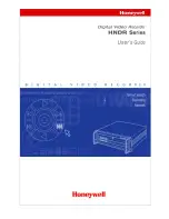
CAM1
CAM5
CAM9
CAM13
CAM2
CAM6
CAM10
CAM14
CAM3
CAM7
CAM11
CAM15
CAM4
CAM8
CAM12
CAM16
2012-02-24 10:06:56
PICTURE 4-25
PICTURE 4-26
PICTURE 4-27
PICTURE 4-28
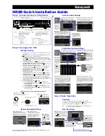
DEFAULT
Select all
GENERAL
SCHEDULE
NETWORK
DETECT
DISPLAY
REMOTE DEVICE
ENCODE
RS232
ALARM
PAN/TILT/ZOOM
Channel Name
OK
Cancel
Please select setting entries that you want to default
WARNING!
Language, time display mode, video format, IP address, and user
account will not retain your settings after being reset back to default values!
DEFAULT
The options in this window will allow you to return various settings back to their default
configuration.
The settings that will be changed are
self-explanatory.
4.5 REMOTE DEVICE
While cameras connected directly to the NVR through the POE ports will automatically
connect and display video, remote cameras connected to your system must be located
and added manually. This can be done through the process described in
Section 2.4 IP
Cameras
at the beginning of this manual or through the
Remote Device
window.
Use of remote devices requires that your NVR is connected to a router. These devices can
be IP cameras or even QC-series DVRs. If you intend to connect to devices that are located
outside of your local network, then this router must be able to access the Internet. Instructions
for connecting your system to the Internet are presented in the
Remote Monitoring Guide
that also came on the CD with your system. It is also available from our online resource at
www.Q-See.com/Support
.
Similarly, the remote devices must be able to communicate with the local network or Internet.
This will be covered in
Chapter 4
of the
Remote Monitoring Guide
as well.
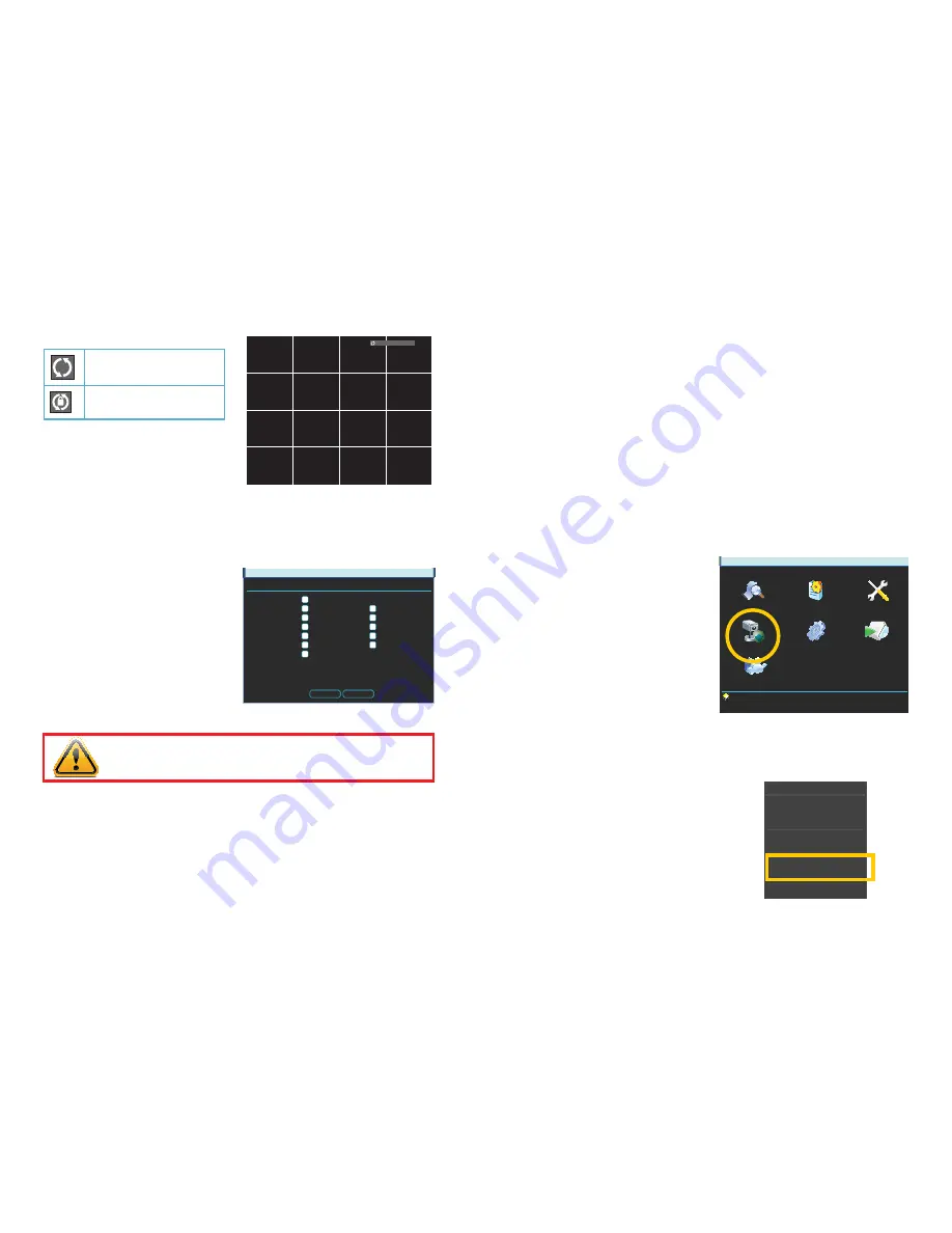
This window can be reached by clicking on
the
Remote Device
icon in the
Main
menu...
MAIN MENU
SEARCH
INFO
SETTING
ADVANCED
BACKUP
REMOTE DEVICE
SHUTDOWN
...or through the
Shortcut
menu by right-
clicking on the screen and selecting
Remote
Device
.
View 1
View 4
View 8
View 9
View 16
Pan/Tilt/Zoom
Color Setting
Search
Record
Remote Device
Alarm Output
Main Menu