SECTION 3 – SYSTEM DESIGN
UL EX3830 ULC EX3830
PagE 3-2 REV. 06 2014-NOV-10
KITCHEN KNIGHT II Restaurant Fire Suppression Manual
NOZZLE COVERAGE AND PLACEMENT (Continued)
Duct Protection (Continued)
Modularizing Ducts –
DUCT SIzES gREaTER THaN 100 IN. (2540 mm) PERIMETER
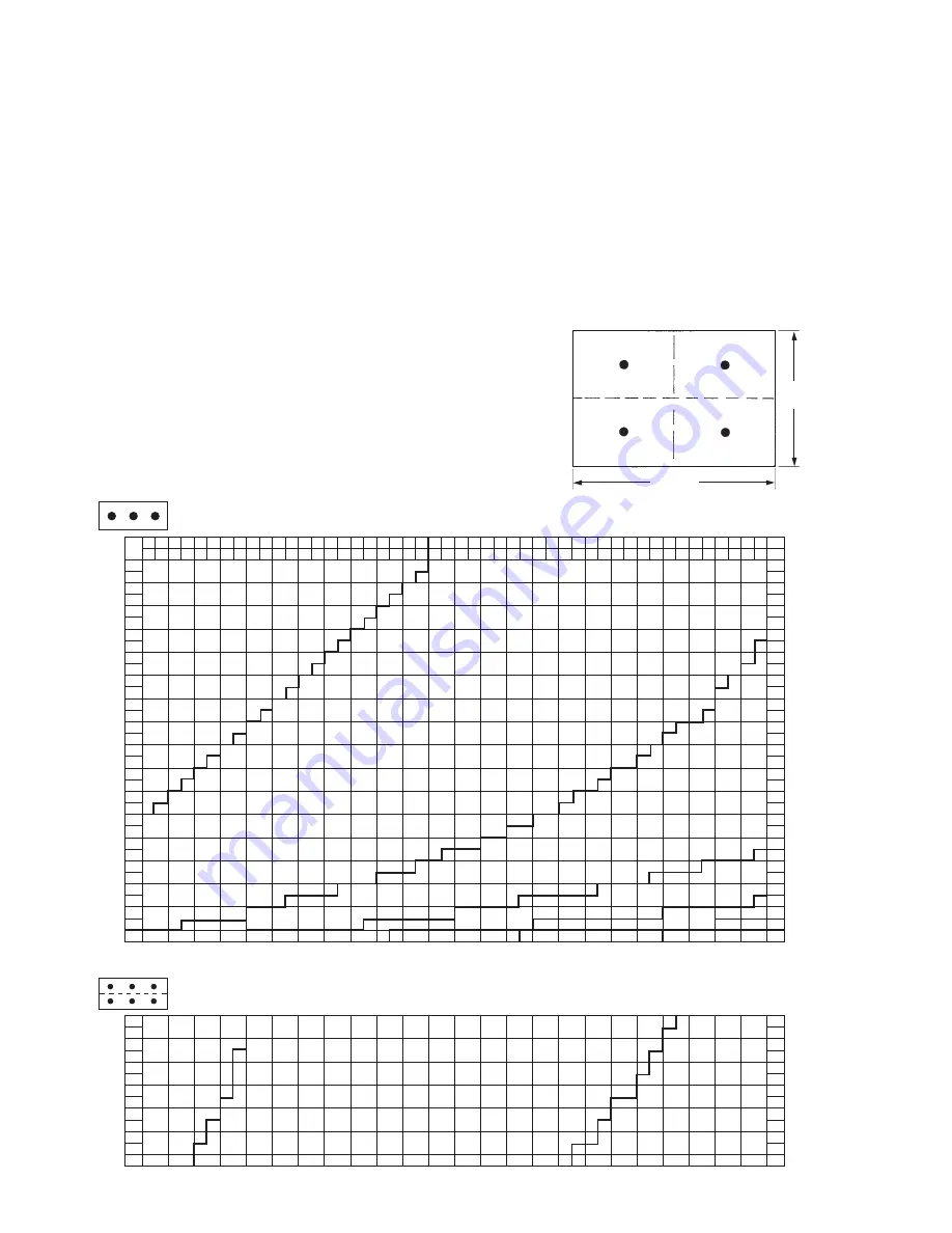
• Ducts over 100 in. perimeter must be modularized using 2D
nozzles (Part No. 551038)
• No round duct option available
• Follow the design chart to determine maximum module size
for each 2D nozzle
• When determining number of nozzles required, it is sometimes
an advantage to check the chart using the shortest side as
Side “a” and then recheck it using the longest side as Side
“a.” This comparison may reveal a need for a lesser quantity
of nozzles one way versus the other way.
When working with Chart 3-1, the quantity of nozzles determined
must be equally divided within the duct area.
When working with Chart 3-2, one half of the quantity of nozzles
determined must be equally positioned in the top half of the area
of the duct and the remaining half of the nozzles must be posi-
tioned in the bottom half of the duct area.
Example: The duct to be protected has a Side “a” of 40 in. (1016
mm) and a Side “B” of 60 in. (1524 mm). Referring to the design
chart, this duct requires 4 nozzles. One half of 4 = 2. Therefore,
2 nozzles must be equally positioned in each of the two duct
areas. See Figure 3-2.
FIGuRE 3-1b
006523
25
4
5
6
7
8
9
10
11
12
13
14
15
16
17
18
19
20
21
22
23
24
25
26
27
28
29
30
31
32
33
34
35
36
10
13
15
18
20
23
25
28
30
33
36
38
41
43
46
48
51
53
56
58
61
64
66
69
71
74
76
79
81
84
86
89
91
91
94
97
99
102
104
107
109
112
114
117
119
122
36
37
38
39
40
41
42
43
44
45
46
47
48
6
7
6
5
26
28
30
32
34
36
38
40
42
44
46
48
50
52
54
56
58
60
62
64
66
68
70
72
27
29
31
33
35
37
39
41
43
45
47
49
51
53
55
57
59
61
63
65
67
69
71
1
2
3
2
4
4
5
6
64 66 69 71 74 76 79 81 84 86 89 91 94 97 99 102 104 107 109 112 114 117 119 122 124 127 130 132 135 137 140 142 145 147 150 152 155 157 160 163 165 168 170 173 175 178 180 183
in.
cm
CHART 3-1
SIDE “B”
in.
cm
in. cm
in. cm
SIDE
“A”
CHART 3-2
A
A
NOTE
: NOzzLE qUaNTITIES LISTED IN CHaRT 3-2 MUST BE EqUaLLY DIVIDED INTO EaCH OF THE TWO DUCT MODULES.
006522
B
B
60 IN.
(1524 mm)
40 IN.
(1016 mm)
30 IN. (762 mm)
30 IN. (762 mm)
20 IN.
(508 mm)
20 IN.
(508 mm)
SIDE “B”
SIDE
“A”
FIGuRE 3-2


