background image

Fire Control Panel

Part Number 151068D, 02/02

SK-4224

Installation and
Operation Manual

firealarmresources.com

Содержание SK-4224

Страница 1: ...Fire Control Panel Part Number 151068D 02 02 SK 4224 Installation and Operation Manual firealarmresources com...

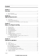
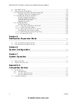
Страница 2: ...7 Assembly 3 6 3 8 Wiring Specifications 3 7 3 9 Calculating Current Draw and Standby Battery 3 8 3 9 1 Worksheet Requirements 3 8 Filling in the Current Draw Worksheet Table 3 6 Section 3 9 3 3 8 3 9...

Страница 3: ...ting the SK 2880 to the SK 2884 4 14 4 7 3 2 Setting the SK 2880 Address 4 14 4 7 3 3 Open Collector Outputs P1 P2 and P3 4 15 Wiring SK 2880 Open Collector Outputs 4 16 4 7 3 4 SK 2880 Input Switches...

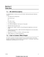
Страница 4: ...put 5 amp max for powering special applications such as door holders Enhanced Verification Mode a built in feature that distinguishes two wire smoke detec tors from pull stations Housed in a 12 13 16...

Страница 5: ...Model SK 4224 Fire Alarm Control Panel Installation Operation Manual 1 2 151068 firealarmresources com...

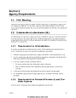
Страница 6: ...ral requirements are described in this section When installing an individual device refer to the specific section of the manual for additional requirements 1 All field wiring must be installed in acco...

Страница 7: ...Model SK 4224 Fire Alarm Control Panel Installation Operation Manual 2 2 151068 firealarmresources com...

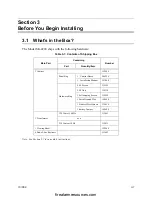
Страница 8: ...Containing Number Part Quantity Item 1 Cabinet 122509 Panel Bag 1 Control Board 204224 1 Installation Manual 151068 Hardware Bag 2 8 Screws 119152 2 8 Nuts 119538 3 Self tapping Screws 119296 1 Earth...

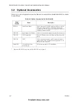
Страница 9: ...4224 expansion devices to the SK 4224 panel Supports1 DACT Model SK 2104 and any combination of 4 LED Annunciators Model SK 2866 or I O Modules Model SK 2880 SK 2880 Input Output I O Module Used to dr...

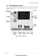
Страница 10: ...s and LEDs Figure 3 1 Model SK 4224 Layout Zone Initiating Circuits 4 Class B or 2 Notification Appliance Circuits Notification Expansion Inputs Trouble Alarm Relays Auxiliary Power Output Backup Batt...

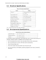
Страница 11: ...ection ports Do not mount in areas with humidity generating equipment such as dryers production machinery Table 3 3 Electrical Specifications Circuit Rating Primary AC 120 Vrms at 60 Hz or 230 Vrms at...

Страница 12: ...on concrete especially when moisture is expected attach a piece of 3 4 inch plywood to the concrete surface and then attach the cabinet to the plywood Also mount any other modules to the plywood Follo...

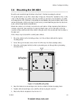
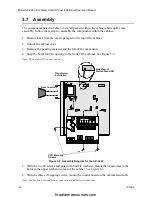
Страница 13: ...mponents 4 Snap the bezel into the opening in the front of the cabinet See Figure 3 3 Note The bezel will fit in only one way Figure 3 3 Assembly Diagram for the SK 4224 5 With the two 8 screws and nu...

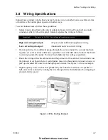
Страница 14: ...he same conduit If you must run them together do so for as short a distance as possible or use shielded cable Connect the shield to circuit ground at the panel You must route high and low voltages sep...

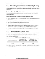
Страница 15: ...5 Make sure that the alarm current without the panel Lines B D does not exceed 2 5 A The total alarm current including the panel Lines A D should not exceed 2 75 A 6 Complete the remaining instruction...

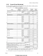
Страница 16: ...device manual for current ratings See Appendix to this manual for max per loop Standby mA mA Alarm mA mA Standby mA mA Alarm mA mA Standby mA mA Alarm mA mA Standby mA mA Alarm mA mA B Current Subtot...

Страница 17: ...Model SK 4224 Fire Alarm Control Panel Installation Operation Manual 3 10 151068 firealarmresources com...

Страница 18: ...necessary for a professional electrician to make this connection The AC inputs are rated as 120 VAC 60 Hz for transformer P N 115061 or 230 VAC 50 Hz for transformer P N 115031 See Table 3 1 for more...

Страница 19: ...e AH rating Determine the correct AH rating as per your current load calculation see Table 3 6 Wire batteries in series to produce a 24 volt equivalent Do not parallel batteries to increase the AH rat...

Страница 20: ...3 N O Contact Wiring 4 3 2 Two Wire Smoke Detector Wiring Figure 4 4 shows how to connect two wire smoke detectors to the SK 4224 initiating circuits The figure uses Silent Knight s SLK 24F with HSB...

Страница 21: ...Installation Figure 4 5 illustrates how to connect a UL listed smoke detector to the SK 4224 in a Class A configuration Refer to the Appendix for a list of compatible devices Information on selecting...

Страница 22: ...the SK 4224 initiating circuits The figure uses Silent Knight s SLK 24F with HSC 4R base as an example You can use any UL listed device Refer to the Appendix for a list of compatible devices Informati...

Страница 23: ...Appendix at the end of this manual for a list of compatible appliances For proper operation you must use polarized notification appliances with a model 7628 4 7k ohm end of line EOL resistor on each...

Страница 24: ...Circuit 4 4 Alarm and Trouble Relays The SK 4224 has built in relays for alarm and trouble The alarm relay is energized during any alarm condition The trouble relay is energized during any trouble or...

Страница 25: ...Panel Installation Operation Manual 4 8 151068 4 6 Door Release Wiring Figure 4 9 shows how to configure a door release using an ESL DH series door holder Figure 4 9 Door Release Wiring Door Holder ES...

Страница 26: ...to the SK 4224 control panel Follow these steps to install the SK 2884 Serial Driver Board 1 Unplug the AC power connector from the SK 4224 control panel See Figure 4 1 2 Unplug the battery connector...

Страница 27: ...r The SK 2866 is used as a remote LED annunciator unit for the SK 4224 SK 2866 Electrical Specification Wiring the SK 2866 to the SK 2884 Follow these steps to properly wire the SK 2866 to the SK 2884...

Страница 28: ...e wiring as shown in Figure 4 11 See also Table 4 2 Figure 4 11 SK 2866 Connection to the SK 2884 Table 4 2 SK 2866 Wiring Connections SK 2866 Terminals SK 2884 Terminals D Data D Data Supervised Powe...

Страница 29: ...he LEDs and the clear plastic plate 3 Place the SK 2866 into the standard 3 gang electrical box See Figure 4 12 Figure 4 12 Mounting the SK 2866 4 Place the cover plate over the top of the SK 2866 and...

Страница 30: ...Figure 4 16 Figure 4 13 Components of the SK 2880 I O Module SK 2880 Specifications Table 4 4 Specifications Circuit Rating Max Circuit Resistance Data 25 25 25 Max Current Alarm 35 mA Standby 35 mA...

Страница 31: ...dule to the Serial Interface Board Figure 4 14 I O Module Wiring 4 7 3 2 Setting the SK 2880 Address The range of valid addresses is 0 3 Each serial device SK 2866 included requires a unique address S...

Страница 32: ...Pin 10 Zone 4 Alarm Supervisory Outputs when there is an alarm or supervisory on Zone 4 Pin 11 Zone 4 Trouble Outputs when a trouble condition exists on Zone 4 Pin 12 Zone 4 Clean Me Trouble Outputs...

Страница 33: ...7 Low AC Outputs if the control panel looses AC power or AC power drops below the control panels low AC threshold Pin 8 Low Battery Outputs when the backup battery voltage drops below 20 4 VDC Pin 9 G...

Страница 34: ...trates how to configure the inputs switches and the Form C Relays Figure 4 16 Wiring Examples for Input Switches and Form C Relays Note Reset and Silence switches must be UL Recognized switches Reset...

Страница 35: ...hing outward on the base retain ing tabs and lift the circuit board out See Figure 4 17 Figure 4 17 Circuit Board and Plastic Base Components 3 Mount the plastic base in a UL listed enclosure using an...

Страница 36: ...circuits 5 1 Class A Notification Expansion Wiring Figure 5 1 shows Class A supervised wiring from a host panel to the SK 4224 control board Observe the proper polarity when making wire connections an...

Страница 37: ...re alarm control panel to the SK 4224 control panel Use an EOL resistor as shown in Figure 5 2 to supervise the FACP input The host fire alarm control panel may use an EOL with a value other than 4 7...

Страница 38: ...s and smoke verification are used in the same zone SW1 SW6 SW1 SW6 ON Enhanced OFF Normal Alarm verification Note Do not use with smoke detectors that have veri fication built in SW 2 SW 7 SW 2 SW 7 O...

Страница 39: ...to the control panel OFF No Serial DACT connected to the control panel AC loss report delay SW7 ON 6 hour delay on AC loss report OFF No delay on AC Note If there is not a serial DACT connected to th...

Страница 40: ...hing press the ACK button to acknowledge the condition GENERAL TROUBLE yellow ON System trouble OFF System OK FLASHING At least one serial device is in trouble DOUBLE FLASHING Two types of serial devi...

Страница 41: ...en acknowledged OFF No zone trouble FLASHING Zone has a trouble condition not yet acknowledged DOUBLE FLASHING Zone was disabled If flashing press the ACK button to acknowledge the condition CLEAN ME...

Страница 42: ...dition Begin Walk Test Press WALK TEST Walk Test LED turns on Note Walk test will not activate if the control panel has a trouble alarm or su pervisory condition End Walk Test The test ends automatica...

Страница 43: ...Model SK 4224 Fire Alarm Control Panel Installation Operation Manual 7 4 151068 firealarmresources com...

Страница 44: ...ctors are used on any zone false alarms could occur Warning Do not mix different models or manufacturers of smoke detectors on the input loops A 1 1 Enhanced Mode Enhanced mode allows the installer to...

Страница 45: ...01 P55FE1 FE51A FE01A 28 PSD 7156 2 Wire 70 201000 001 P56FE1 FE51A FE01A 28 Apollo 4 55000 350 45681 200 55000 350 45681 200 24 4 55000 250 45681 200 55000 250 45681 200 24 Detection Systems DS250 MB...

Страница 46: ...2WB 2WRLT 2WRB P56FE1 FE51A FE01A 28 PSD 7156 CPD 001 002 003 005 P56FE1 FE51A FE01A 28 SBS 1101 A N A 20 SBS 1201 A N A 20 SBS 1201T A N A 20 System Sensor 1100 A N A 20 loop 1100T A N A 20 loop 110...

Страница 47: ...N A 20 loop 2451 B401B A N A 20 loop 2451DH DH 400 A N A 20 loop 2451TH B401B A N A 20 loop 2800 A N A 20 loop 2800TH A N A 20 loop 2851B B101B A A 20 loop 2851BTH B101B A A 20 loop 2851DH A A 20 loo...

Страница 48: ...0 MD622 4B 6B M612 912 MD622 4B 6B M612 912 20 MD632 4B 6B M612 912 MD632 4B 6B M612 912 20 MF612 4B 6B M612 912 MF612 4B 6B M612 912 20 MR612 4B 6B M612 912 MR612 4B 6B M612 912 20 MR612T 4B 6B M612...

Страница 49: ...ke Detectors Table A 2 Compatible Four Wire Smoke Detectors Manufacturer Model Silent Knight SD P24F with SD B4 base Detection Systems DS200 DS200HD MB200 ESL 445 Series 449 Series Gentex 624 824 2040...

Страница 50: ...Horn Strobe surface 5338B 4 24 DC Multi Tone Horn Strobe ceiling 5343B 0 14 24 DC Single Tone Horn Strobe flush 5344B 0 14 24 DC Single Tone Horn Strobe surface 5345B 0 4 24 DC Single Tone Horn Strobe...

Страница 51: ...trobe Strobe surface 6312B 14 24 DC Mini Horn Strobe Strobe ceiling 6320B 0 14 24 DC Sync Mini Horn Strobe 1 gang 6321B 0 14 24 DC Sync Mini Horn Strobe 1 2 gang 6322B 14 24 DC Mini Horn Sync Strobe 1...

Страница 52: ...475K FC Strobe S24110 FC Strobe S24110W FC Strobe S24110K FC Strobe MDL FC Sync Module MDLW FC Sync Module Federal Signal 450 Horn VALS Horn Strobe Gentex GX90 4 Horn GXS 4 15 1 Strobe GXS 4 1575 Stro...

Страница 53: ...n Strobe P2415K Horn Strobe P241575 Horn Strobe P241575W Horn Strobe P241575F Horn Strobe P241575K Horn Strobe P2430 Horn Strobe P2430W Horn Strobe P2430K Horn Strobe P2475 Horn Strobe P2475W Horn Str...

Страница 54: ...ne Horn AES EL1 WS 24 VF R Multitone Horn AES DL1 WH 24 VF R Multitone Horn AES EL1 WH 24 VF R Multitone Horn AES DL1 WM 24 VF R Multitone Horn AES EL1 WM 24 VF R Multitone Horn AH 24 R Horn AH 24WP R...

Страница 55: ...FR Chime Strobe CH70 2475W FR Chime Strobe CH70 24110W FR Chime Strobe CH CF1 Chime CH CF1 R Chime CH CF1 W Chime CH DF1 Chime CH DF1 R Chime CH BF1 WS 24 HF R Strobe Chime CH CF1 LS 24 Strobe Chime C...

Страница 56: ...e Strobe IS 24 VFR Remote Strobe IS1 24 VFR Remote Strobe IS3 24 VFR Remote Strobe ISP 24 HFR Remote Strobe LS 24 VFR Remote Strobe LS1 24 VFR Remote Strobe LS3 24 VFR Remote Strobe LSP 24 HFR Remote...

Страница 57: ...Strobe Horn MT 24 SLM VFR Synch Multitone Strobe MT 24 WM Strobe MT 24 WM VF R Horn MT 24 WM VFR Strobe Horn NH 12 24 R Horn NS 2415W FR Strobe Horn NS 241575W FR Strobe Horn NS 2430W FR Strobe Horn N...

Страница 58: ...Strobe SLM 24 VFR Synchronized Remote Strobe SL1M 24 VFR Synchronized Remote Strobe SL3M 24 VFR Synchronized Remote Strobe SLPM 24 VFR Synchronized Remote Strobe SHW 24 VFR Synchronized Remote Strobe...

Страница 59: ...larm Control Panel Installation Operation Manual A 16 151068 Wheelock Cont WS1T 24 FR Strobe WS3T 24 FR Strobe WST 24 FR Strobe Table A 3 Compatible Notification Appliances Manufacturer Model Type fir...

Страница 60: ...the condition CLEAN ME FLASHING Indicates that the smoke detector needs cleaning A Clean Me Flash is a flash with a long LED on Time and a short LED off time indicating that the smoke detector needs...

Страница 61: ...Cut Along the Dotted Line firealarmresources com...

Страница 62: ...oblem should be included with each return All products returned to Silent Knight must be sent freight pre paid After product is pro cessed Silent Knight will pay for shipping product back to customer...

Страница 63: ...ts in materials or workmanship for 18 months from the manufacturing date code on the printed circuit board if such goods have been properly installed are subject to normal proper use and have not been...

Страница 64: ...2002 Silent Knight Part Number 151068D 02 02 7550 Meridian Circle Maple Grove MN 55369 4927 763 493 6455 1 800 328 0103 Fax 763 493 6475 firealarmresources com...
Отзывы: