


Model SK-4224 Fire Alarm Control Panel Installation/Operation Manual
4-14
151068
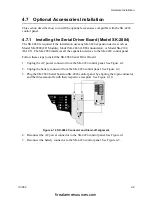
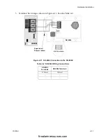
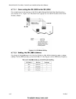
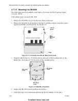
4.7.3.1 Connecting the SK-2880 to the SK-2884
The control panel communicates to the I/O module through the Serial Interface Board (see
also Section 4.7.1). Figure 4-14 illustrates how to properly wire the I/O module to the Serial
Interface Board.
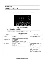
Figure 4-14 I/O Module Wiring
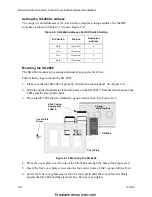
4.7.3.2 Setting the SK-2880 Address
The range of valid addresses is 0-3. Each serial device (SK-2866 included) requires a unique
address. Set the DIP switches as shown in Table 4-5. See Figure 4-14 for DIP switch location.
Table 4-5: SK-2880 Addresses Per DIP Switch Setting
DIP Switch
Position
Address
Both
Open (off)
0
One
Closed (on)
1
Two
Closed (on)
2
Both
Closed (on)
3
Supervised
Power Limited
SK-2880
SK-2884
firealarmresources.com
Содержание SK-4224
Страница 5: ...Model SK 4224 Fire Alarm Control Panel Installation Operation Manual 1 2 151068 firealarmresources com...
Страница 7: ...Model SK 4224 Fire Alarm Control Panel Installation Operation Manual 2 2 151068 firealarmresources com...
Страница 17: ...Model SK 4224 Fire Alarm Control Panel Installation Operation Manual 3 10 151068 firealarmresources com...
Страница 43: ...Model SK 4224 Fire Alarm Control Panel Installation Operation Manual 7 4 151068 firealarmresources com...
Страница 61: ...Cut Along the Dotted Line firealarmresources com...


