


SECTION 4
Pronar T286
4.18
MARKINGS
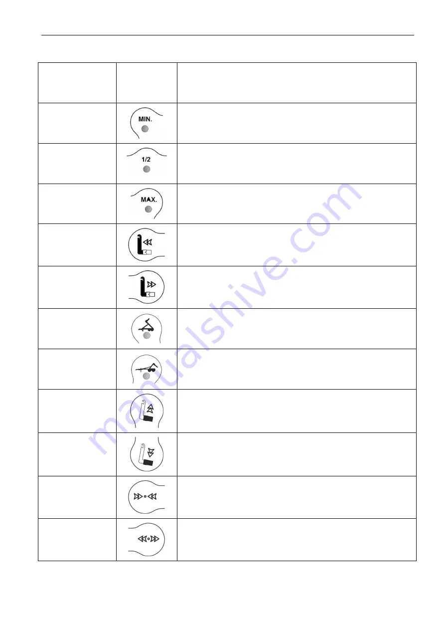
ON FIGURE 4.7
SYMBOL
OF
FUNCTION
DESCRIPTION
4
Indicator light signalling that the rear fender is folded
(tipping frame control function is unlocked).
5
Indicator light signalling that the rear fender is halfway the
extension range.
6
Indicator light signalling that the rear fender is at the
maximum position.
7
Push-button for extending the telescopic hook frame.
8
Push-button for withdrawing the telescopic hook frame.
9
Indicator light signalling that the trailer is in "tipper"
operation mode.
10
Indicator light signalling that the trailer is in "hook trailer"
operation mode.
11
Push-button for rising the tipping frame.
12
Push-button for lowering the tipping frame.
13
Push-button for withdrawing the load box interlock.
14
Push-button for extending the load box interlock.
Содержание T286
Страница 2: ......
Страница 6: ......
Страница 11: ...SECTION 1 BASIC INFORMATION ...
Страница 25: ...SECTION 2 SAFETY ADVICE ...
Страница 41: ...SECTION 3 DESIGN AND OPERATION ...
Страница 75: ...SECTION 4 CORRECT USE ...
Страница 117: ...SECTION 5 MAINTENANCE ...
Страница 155: ...SECTION 5 Pronar T286 5 39 FIGURE 5 14 Trailer s lubrication points part 1 ...
Страница 156: ...Pronar T286 SECTION 5 5 40 FIGURE 5 15 Trailer s lubrication points part 2 ...
Страница 165: ...NOTES ...
Страница 166: ... ...


