The cubic feet per hour of gas required is determined by
dividing the maximum burner input in Btu/h as marked on
the rating plate by the calorific value (Btu value) of the fuel
required.
1. Refer to the Mechanical Arrangement Drawing to
determine the location of the gas connection. Ensure
that gas piping does not interfere with the removal of any
access door or hinder servicing of the unit in any way.
2. An emergency manual shut-off valve shall be provided
upstream of the piping to the unit and should be labeled
for quick identification. Color coding of the gas piping is
also recommended.
3. High pressure gas regulators, if required, should be
located at least five feet (1.5 m) upstream from the
appliance regulator on the unit.
4. A 1/8” (3 mm) NPT plugged tapping for test gauge
connection must be installed immediately upstream of the
gas supply connection to the appliance.
5. High gas pressure regulator (if equipped), appliance
regulator, high pressure pilot pressure regulator (if
supplied), gas pressure switch (if supplied) and normally
open vent valve (if supplied) must be vented to the outside
of the building for an indoor unit. Do not use copper for
vent lines. Aluminum or stainless steel are acceptable.
Refer to National Fuel Gas Code, ANSI Z223.1/NFPA 54,
or the Natural Gas and Propane Installation Code, CSA
B149.1.
6. Before connecting the gas piping to the burner, determine
that the unit has been designed for use with the gas to
which it is to be connected. DO NOT attempt to convert
the unit from the fuel specified on the rating to use with
another fuel without consulting with the local gas utility
and Price Industries for instruction.
7. The appliance and its individual shut-off valve must be
disconnected from the gas supply piping system during
any pressure testing at test pressures in excess of ½ psi
(3.5Kpa). The appliance must be isolated from the gas
supply piping system by closing its individual manual shut-
off valve during any pressure testing of the gas supply
piping system at test pressures equal to or less than ½ psi
(3.5Kpa).
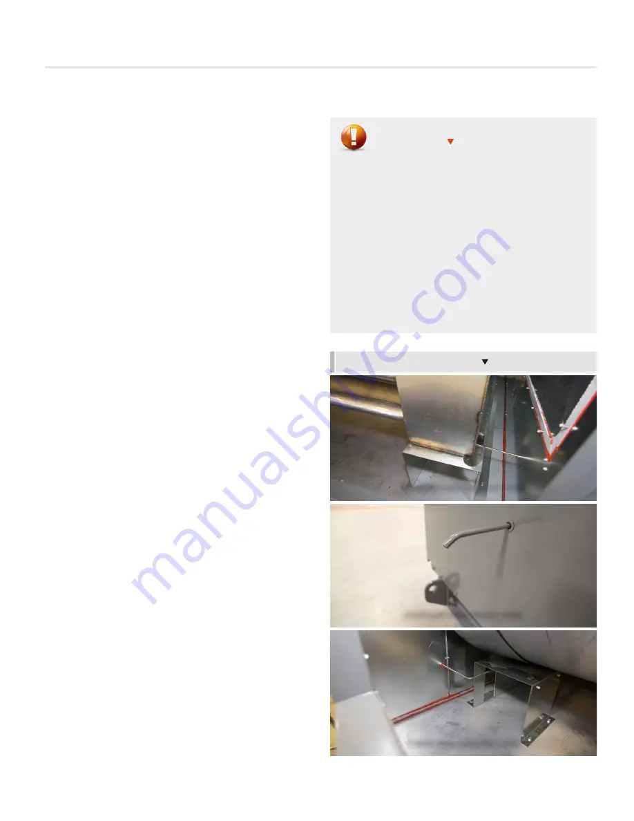
Gas Condensate Drain
IMPROPER CONDENSATE TRAP CAN LEAD TO HEAT EXCHANGER
DAMAGE:
If the heat exchanger is not properly trapped,
the condensate may not drain and it may lead to heat
exchanger corrosion. A hole in the heat exchanger is an
unsafe situation and the unit cannot be operated. Failure
of the heat exchanger due to improper condensate
trapping will void the warranty.
All AW-I series units are equipped with furnace
condensate drain connection(s). Provisions shall be made
to properly dispose of the condensate according to the
local codes. The furnace condensate lines should be
trapped in the field to avoid injury from potential hot gases.
FURNACE CONDENSATE DRAINS
WARNING
PRIMARY DRUM CONDENSATE DRAIN
CONDENSATE DRAIN THROUGH CASING
SECONDARY TUBES CONDENSATE DRAIN
14
AW-I
INSTALLATION INSTRUCTIONS
AW-I - Manual
|
priceindustries.com
Содержание AW-I Series
Страница 37: ...35 AW I NOTES priceindustries com AW I Manual...
Страница 38: ...36 AW I NOTES AW I Manual priceindustries com...
Страница 39: ...37 AW I NOTES priceindustries com AW I Manual...


