Gamatronic Electronic Industries Ltd.
User Guide
µ
PS-SP 3:3, 3x220 in, 3x208 60 Hz out
Communications
37
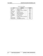
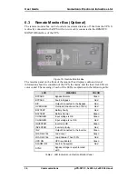
The monitor panel also contains buttons for controlling the UPS which are described
in the following table:
BUTTON
PURPOSE
UPS ON
Not in use
UPS OFF
Not in Use
INV
Manually switches the load from the bypass to the inverter
B/P
Manually switches the load from the inverter to the bypass
BATTERY TEST
Manually starts a battery test
ALARM OFF
Silences the audible alarm
Table 5: Control Buttons on Remote Monitor Panel
6.3.1
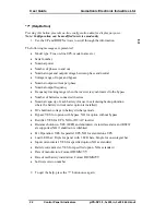
Connecting the Monitor Box to the UPS
1.
Attach the back of the monitor box to the wall.
2.
The UPS PC908 board in the monitor box is connected
to the PC021 board on the rear panel of the UPS with a
4-wire cable connected to the appropriate 1-4 Pin male
or female DB9 connector terminal in the UPS’ row of
terminals.
3.
The cable is attached to the side of the monitor box
with two screws.
DB9
Row of Terminals
The measurements of the Monitor box are: Length - 265mm, height -135 mm, and
distance between the screws on the back of the box - 200mm.


