User Guide Gamatronic Electronic Industries Ltd.
µ
PS-SP 3:3, 3x220 in, 3x208 60 Hz out
Control Panel & Indicators
26
Bit 2: 1 = Fault detected by bi-metal temperature sensor
Bit 7: 1 = Fault exists
Byte 7 shows bypass frequency diagnostics:
Bit 0: 1 = Bypass frequency incorrect
Byte 8 shows over-current diagnostics. Indications are as follows:
Bit 0: 1 = Over-current detected in phase R
Bit 1: 1 = Over-current detected in phase S
Bit 2: 1 = Over-current detected in phase T
Bit 7: 1 = Fault exists
Byte 9 shows load transferring diagnostics. Indications are as follows:
Bit 0: 1 = Transferring started
Bit 1: 1 = Inverter is OFF
Bit 2: 1 = Inverter restarting
Bit 3: 1 = Inverter under diagnosis
Bit 4: 1 = Switching to inverter – SRSW SCR is ON
Bit 5: 1 = Switching to inverter – SRSW SCR is OFF
Bit 6: 1 = System in wait state
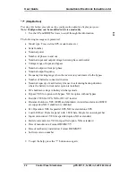
To view the active current sharing status, press the down arrow
.
Iact
IaR
IaS
IaT
Iavr
IavR
IavS
IavT
Figure 11: Active Current Sharing
I and Ia in Figure 14 show the results of active average current measurements on
phases R, S and T using a half-scale offset. Zero current is presented as 128. With
positive current this value increases, with negative current, this value decreases.
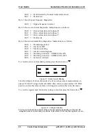
To view the register used for inverter voltage correction, press the down arrow
.
CORR R
R
R
S
R
T
Figure 12: Voltage Correction
R in Figure 12 shows the contents of the correction register, depending on the load, DC
votage abd active current sharing conditions. Initial value of the correction registers is zero.

