User Guide Gamatronic Electronic Industries Ltd.
µ
PS-SP 3:3, 3x220 in, 3x208 60 Hz out
Installation
48
9.3.2
External Battery Cabinet
This section is relevant for all models of the UPS.
The UPS batteries supply a nominal voltage of 192VDC. The battery cabinet houses
16 batteries of 12V each.
1.
Connect the battery cabinet to the UPS with a 3-wire cable (plus,
minus, ground). Be sure to use the proper grade of wire as listed in
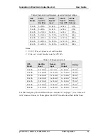
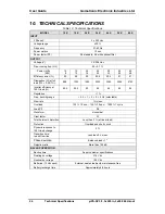
Table 8 on page 43.
2.
An external circuit breaker should be installed between the battery
cabinet and the UPS. The circuit breaker should be a 2-pole type,
rated at 250VDC or better. The battery circuit breaker should be
connected between the Auxiliary terminal of the battery cabinet and
the Battery Test terminal of the UPS, using a 2-wire cable with each
wire having a cross-section of 1 mm
2
. See Figure xx.
3.
The Battery Test function can be used to monitor the status of the
battery circuit breaker. When the circuit breaker is open, a Battery
Test results in a Battery Low alarm.
4.
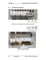
Connect the battery cabinet to the appropriate terminals of the UPS
as shown in Figure 17, on page 44, and according to the schematic in
Figure 20.
UPS GROUND
BUS
UPS
EXTERNAL
BATTERY
CABINET
+
192VDC
Battery
Terminals
Battery Test
Terminals
Battery Test
Terminals
Figure 20: Connecting the external battery cabinet


