Gamatronic Electronic Industries Ltd.
User Guide
µ
PS-SP 3:3, 3x220 in, 3x208 60 Hz out
Control Panel & Indicators
17
4.2.1
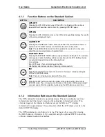
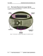
Function Buttons on the Larger Cabinet
BUTTON
DESCRIPTION
UPS ON/OFF
When the UPS is OFF, pressing the UPS ON/OFF button turns on the UPS and
sequentially displays the results of the start-up diagnostic tests
When the UPS is ON, pressing the UPS ON/OFF button turns off the UPS.
Confirmation of this action is required. Wait 2 seconds, and confirm it by pressing
UPS OFF again.
BATT
TEST
BATTERY TEST
Pressing the BATTERY TEST button manually initiates a battery test. The unit also
continuously checks the battery cabinet connection with the UPS. Battery checks
are automatically performed at the following times:
Upon start-up
Every 200 hours of accumulated operating time
After battery cabinet reconnection (following a disconnection)
B/P
INV
B/P INV
When the UPS is in Inverter mode, pressing the B/P INV button connects the
mains to the output, putting the unit into Bypass mode. The unit requires
confirmation of this action. Wait approximately 2 seconds, and confirm the selection
by pressing the B/P INVbutton a second time.
When the UPS is in Bypass mode, pressing the B/P INV button connects the
inverter to the output, manually taking the UPS out of Bypass mode.
Note: There is no display associated with this action.
ALARM OFF
Pressing the ALARM OFF button silences the alarm that sounds when there is a
system fault. If another fault occurs, the alarm returns to active mode.
Note: The ALARM LED remains lit until the problem is resolved to notify users
about the continued existence of a system fault.
4.2.2
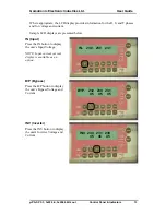
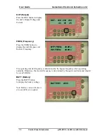
Information Buttons on the Larger Cabinet
The UPS continually monitors its operational status. The user can display real-time
information about this status by pressing the appropriate information button. If an
alarm is triggered, the information buttons (except for LOG and “?”) display
information for approximately 10 seconds, after which the LCD display reverts to the
default STATUS display.
The UPS maintains an event history in its log. The log can be accessed by pressing
the LOG button or, alternatively, by a computer using the optional RS232 connection,
or from a remote location via a modem.
Where appropriate, the LCD display provides information for the R, S, and T phases
and for voltage and current.

