Gamatronic Electronic Industries Ltd.
User Guide
µ
PS-SP 3:3, 3x220 in, 3x208 60 Hz out
Control Panel & Indicators
23
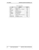
Table 1: Log Variables
Event
LOG Variable
Overload
Sum of currents in all phases
Inverter fault
V
inv
(average inverter voltage) in all phases
Bypass fault
V
byp
(average bypass voltage) in all phases where
there is a bypass voltage fault
or
Hz (Frequency) where there is a bypass frequency
fault
Input fault
Average V
in
on all phases
High temperature
Temperature °C
Rectifier fault, battery low
DC voltage
Other fault
Average V
out
for all phases
Faults are represented as a hexadecimal word comprising 16 bits:
Bit 0: 1 = Overload
Bit 1: Inverter
Bit 2: Bypass
Bit 3: Rectifier
Bit 4: Input
Bit 5: Phase sequence
Bit 6: Temperature
Bit 7: Battery test failure
Bit 8: Output
Bit 9: Load on bypass
Bit 10: Circulation (for parallel)
Bit 11: Slave receive failure (parallel only)
For example, fault 0009H = 0000000000001001 binary which translates as overload and
battery test failure.
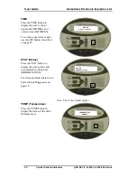
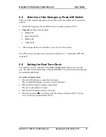
SET (Time)
Pressing this button sets the unit’s real-time clock (see “Setting the Real Time Clock” on
page 33.

