Gamatronic Electronic Industries Ltd.
User Guide
µ
PS-SP 3:3, 3x220 in, 3x208 60 Hz out
Control Panel & Indicators
25
4.4
System Fault Diagnostics
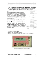
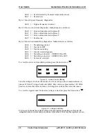
Select the STAT button and press the down arrow
. The display will show 2 bytes
representing the FAULT (see LOG on page 21) followed by two bytes (each of 8 bits)
are now on display, each representing the
STATE
and the
INSTRUCTION
.
To use the hexadecimal indicators, make a note of the bit representations.
The
STATE
byte indications are as follows:
Bit 0: UPS power
1 = ON, 0 = OFF
Bit 1: Load supply 1 = On bypass, 0 = On inverter
Bit 3: Audible alarm 1 = Disabled, 0 = Enabled
Bit 4: Load transfer 1 = In progress, 0 = Pending
Bit 5: Battery check 1 = In progress, 0 = Pending
The
INSTRUCTION
byte indications are as follows:
Bit 0: UPS power
1 = ON, 0 = OFF
Bit 1: Load supply 1 = On bypass, 0 = On inverter
Bit 5: Battery check 1 = In progress, 0 = Pending
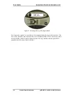
To view fault condition details, press the down arrow
, and 9 bytes are displayed
on the panel:
Byte 1 shows input diagnostics. Indications are as follows:
Bit 0: 1 = Fault is in phase R
Bit 1: 1 = Fault is in phase S
Bit 3: 1 = Fault is in phase T
Bit 7: 1 = Fault exists
Byte 2 shows the result of bypass symptoms analysis.
Byte 3 shows result of inverter symptoms analysis.
Byte 4 shows output voltage diagnostics. Indications are as per byte 1.
Byte 5 shows DC voltage diagnostics. Indications are as follows:
Bit 0: 1 = Battery is currently discharging
Bit 1: 1 = Battery is discharged
Bit 2: 1 = Battery is disconnected
Bit 3: 1 = Battery check failed
Bit 4: 1 = Excessive current difference in battery sets. (Option)
Bit 6: 1 = Rectifier failure
Bit 7: 1 = Fault exists
Byte 6 shows measured temperature diagnostics. Indications are as follows:
Bit 0: 1 = Shutdown limit exceeded
Bit 1: 1 = Alarm limit exceeded


